IGNITION SEQUENCE

First Stage – Trial For Pilot Ignition

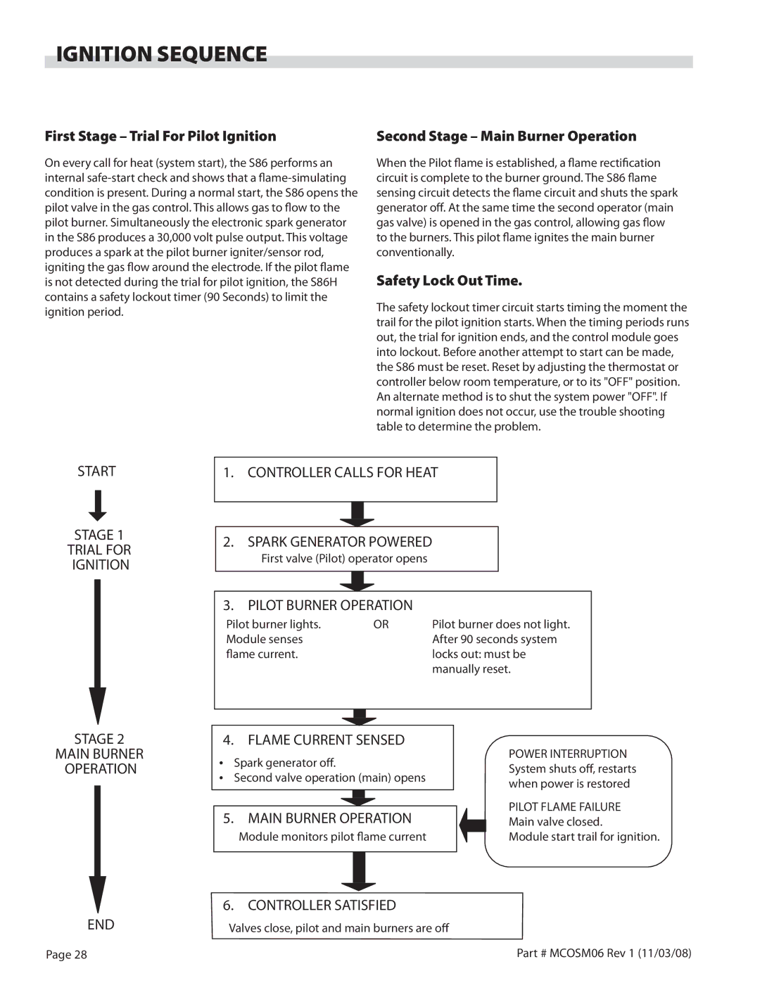
On every call for heat (system start), the S86 performs an internal safe-start check and shows that a flame-simulating condition is present. During a normal start, the S86 opens the pilot valve in the gas control. This allows gas to flow to the pilot burner. Simultaneously the electronic spark generator in the S86 produces a 30,000 volt pulse output. This voltage produces a spark at the pilot burner igniter/sensor rod, igniting the gas flow around the electrode. If the pilot flame is not detected during the trial for pilot ignition, the S86H contains a safety lockout timer (90 Seconds) to limit the ignition period.

Second Stage – Main Burner Operation

When the Pilot flame is established, a flame rectification circuit is complete to the burner ground. The S86 flame sensing circuit detects the flame circuit and shuts the spark generator off. At the same time the second operator (main gas valve) is opened in the gas control, allowing gas flow to the burners. This pilot flame ignites the main burner conventionally.

Safety Lock Out Time.

The safety lockout timer circuit starts timing the moment the trail for the pilot ignition starts. When the timing periods runs out, the trial for ignition ends, and the control module goes into lockout. Before another attempt to start can be made, the S86 must be reset. Reset by adjusting the thermostat or controller below room temperature, or to its "OFF" position. An alternate method is to shut the system power "OFF". If normal ignition does not occur, use the trouble shooting table to determine the problem.

START

STAGE 1

TRIAL FOR IGNITION

1.CONTROLLER CALLS FOR HEAT

2.SPARK GENERATOR POWERED

First valve (Pilot) operator opens

3. PILOT BURNER OPERATION

Pilot burner lights.

OR

Pilot burner does not light.

Module senses


After 90 seconds system

flame current.


locks out: must be


manually reset.

STAGE 2

MAIN BURNER OPERATION

END

Page 28

4.FLAME CURRENT SENSED

Spark generator off.

Second valve operation (main) opens

5.MAIN BURNER OPERATION

Module monitors pilot flame current

6. CONTROLLER SATISFIED

Valves close, pilot and main burners are off

POWER INTERRUPTION System shuts off, restarts when power is restored

PILOT FLAME FAILURE Main valve closed.

Module start trail for ignition.

Part # MCOSM06 Rev 1 (11/03/08)

Page 28
Image 28
Garland 200 service manual Ignition Sequence, First Stage Trial For Pilot Ignition, Second Stage Main Burner Operation

200 specifications

Garland 200 is an innovative and versatile piece of equipment that has made a significant impact in various industries due to its advanced features and technologies. Designed for efficiency and performance, the Garland 200 stands out with its unique combination of high-quality materials and cutting-edge engineering.

One of the primary characteristics of the Garland 200 is its robust construction. Built to withstand rigorous demands, it employs a heavy-duty frame that ensures durability and longevity. This makes it an ideal choice for both indoor and outdoor applications, as it can endure harsh environmental conditions while maintaining optimal performance.

The Garland 200 features an intuitive control interface, which enhances user experience by making operations straightforward and efficient. The user-friendly design allows operators to quickly adapt to the equipment, minimizing the learning curve and ensuring a smooth workflow. With its easy-to-navigate controls, users can make adjustments on-the-fly, improving overall productivity.

Incorporating state-of-the-art technologies, the Garland 200 is equipped with advanced sensors that monitor performance in real-time. This feature not only enhances the safety of operations but also allows for proactive maintenance, reducing downtime and extending the equipment's lifespan. Users benefit from detailed analytical data that can lead to informed decision-making, optimizing productivity.

Additionally, the Garland 200 is designed with energy efficiency in mind. It employs energy-saving technologies that reduce consumption while maintaining superior performance levels. This commitment to sustainability not only lowers operational costs but also aligns with modern environmental standards.

Another notable feature is its versatility. The Garland 200 is compatible with a range of attachments and accessories, allowing it to adapt to various tasks and requirements easily. This flexibility makes it a favorite among professionals in landscaping, construction, and other demanding fields.

Overall, the Garland 200 has become a reliable choice for those seeking a powerful and efficient solution for their operational needs. With its combination of durability, advanced technology, user-friendly features, and energy efficiency, it sets a new standard in its category. As industries continue to evolve, the Garland 200 stands ready to meet the challenges of tomorrow.