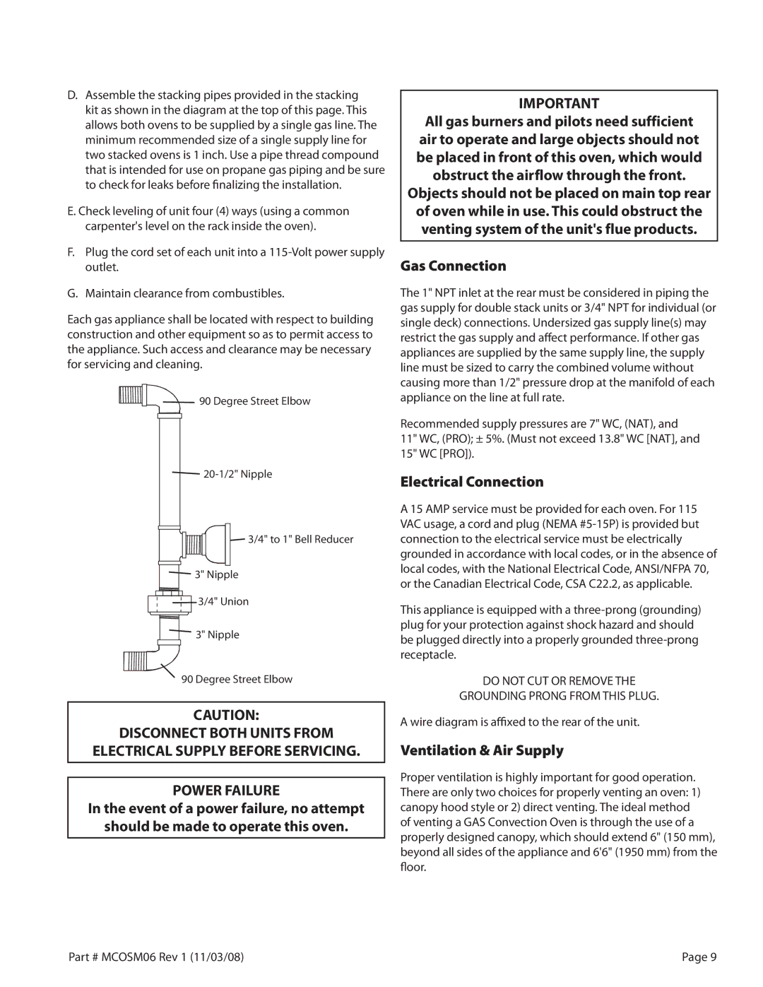
D.Assemble the stacking pipes provided in the stacking kit as shown in the diagram at the top of this page. This allows both ovens to be supplied by a single gas line. The minimum recommended size of a single supply line for two stacked ovens is 1 inch. Use a pipe thread compound that is intended for use on propane gas piping and be sure to check for leaks before finalizing the installation.

E.Check leveling of unit four (4) ways (using a common carpenter's level on the rack inside the oven).

F.Plug the cord set of each unit into a 115-Volt power supply outlet.

G.Maintain clearance from combustibles.

Each gas appliance shall be located with respect to building construction and other equipment so as to permit access to the appliance. Such access and clearance may be necessary for servicing and cleaning.

90 Degree Street Elbow

20-1/2" Nipple

3/4" to 1" Bell Reducer

3" Nipple

3/4" Union

3" Nipple

90 Degree Street Elbow

CAUTION:

DISCONNECT BOTH UNITS FROM

ELECTRICAL SUPPLY BEFORE SERVICING..

POWER FAILURE

In the event of a power failure, no attempt

should be made to operate this oven..

IMPORTANT

All gas burners and pilots need sufficient air to operate and large objects should not be placed in front of this oven, which would obstruct the airflow through the front..

Objects should not be placed on main top rear of oven while in use.. This could obstruct the venting system of the unit's flue products..

Gas Connection

The 1" NPT inlet at the rear must be considered in piping the gas supply for double stack units or 3/4" NPT for individual (or single deck) connections. Undersized gas supply line(s) may restrict the gas supply and affect performance. If other gas appliances are supplied by the same supply line, the supply line must be sized to carry the combined volume without causing more than 1/2" pressure drop at the manifold of each appliance on the line at full rate.

Recommended supply pressures are 7" WC, (NAT), and 11" WC, (PRO); ± 5%. (Must not exceed 13.8" WC [NAT], and 15" WC [PRO]).

Electrical Connection

A 15 AMP service must be provided for each oven. For 115 VAC usage, a cord and plug (NEMA #5-15P) is provided but connection to the electrical service must be electrically grounded in accordance with local codes, or in the absence of local codes, with the National Electrical Code, ANSI/NFPA 70, or the Canadian Electrical Code, CSA C22.2, as applicable.

This appliance is equipped with a three-prong (grounding) plug for your protection against shock hazard and should be plugged directly into a properly grounded three-prong receptacle.

DO NOT CUT OR REMOVE THE

GROUNDING PRONG FROM THIS PLUG.

A wire diagram is affixed to the rear of the unit.

Ventilation & Air Supply

Proper ventilation is highly important for good operation. There are only two choices for properly venting an oven: 1) canopy hood style or 2) direct venting. The ideal method of venting a GAS Convection Oven is through the use of a properly designed canopy, which should extend 6" (150 mm), beyond all sides of the appliance and 6'6" (1950 mm) from the floor.

Part # MCOSM06 Rev 1 (11/03/08)

Page 9

Page 9
Image 9
Garland 200 service manual Gas Connection, Electrical Connection, Ventilation & Air Supply

200 specifications

Garland 200 is an innovative and versatile piece of equipment that has made a significant impact in various industries due to its advanced features and technologies. Designed for efficiency and performance, the Garland 200 stands out with its unique combination of high-quality materials and cutting-edge engineering.

One of the primary characteristics of the Garland 200 is its robust construction. Built to withstand rigorous demands, it employs a heavy-duty frame that ensures durability and longevity. This makes it an ideal choice for both indoor and outdoor applications, as it can endure harsh environmental conditions while maintaining optimal performance.

The Garland 200 features an intuitive control interface, which enhances user experience by making operations straightforward and efficient. The user-friendly design allows operators to quickly adapt to the equipment, minimizing the learning curve and ensuring a smooth workflow. With its easy-to-navigate controls, users can make adjustments on-the-fly, improving overall productivity.

Incorporating state-of-the-art technologies, the Garland 200 is equipped with advanced sensors that monitor performance in real-time. This feature not only enhances the safety of operations but also allows for proactive maintenance, reducing downtime and extending the equipment's lifespan. Users benefit from detailed analytical data that can lead to informed decision-making, optimizing productivity.

Additionally, the Garland 200 is designed with energy efficiency in mind. It employs energy-saving technologies that reduce consumption while maintaining superior performance levels. This commitment to sustainability not only lowers operational costs but also aligns with modern environmental standards.

Another notable feature is its versatility. The Garland 200 is compatible with a range of attachments and accessories, allowing it to adapt to various tasks and requirements easily. This flexibility makes it a favorite among professionals in landscaping, construction, and other demanding fields.

Overall, the Garland 200 has become a reliable choice for those seeking a powerful and efficient solution for their operational needs. With its combination of durability, advanced technology, user-friendly features, and energy efficiency, it sets a new standard in its category. As industries continue to evolve, the Garland 200 stands ready to meet the challenges of tomorrow.