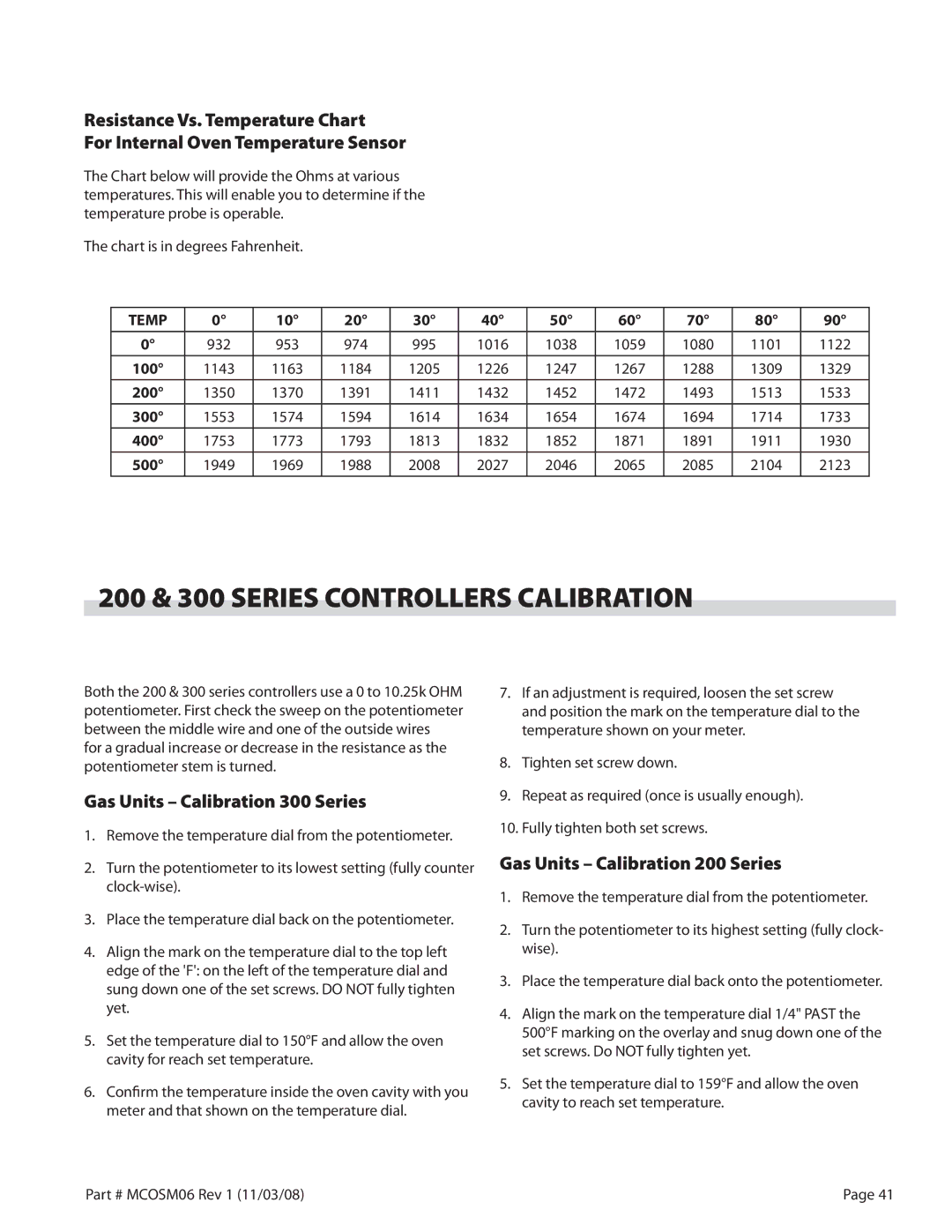
Resistance Vs. Temperature Chart

For Internal Oven Temperature Sensor

The Chart below will provide the Ohms at various temperatures. This will enable you to determine if the temperature probe is operable.

The chart is in degrees Fahrenheit.

TEMP

10°

20°

30°

40°

50°

60°

70°

80°

90°


932

953

974

995

1016

1038

1059

1080

1101

1122

100°

1143

1163

1184

1205

1226

1247

1267

1288

1309

1329


200°

1350

1370

1391

1411

1432

1452

1472

1493

1513

1533


300°

1553

1574

1594

1614

1634

1654

1674

1694

1714

1733

400°

1753

1773

1793

1813

1832

1852

1871

1891

1911

1930


500°

1949

1969

1988

2008

2027

2046

2065

2085

2104

2123


200 & 300 SERIES CONTROLLERS CALIBRATION

Both the 200 & 300 series controllers use a 0 to 10.25k OHM potentiometer. First check the sweep on the potentiometer between the middle wire and one of the outside wires

for a gradual increase or decrease in the resistance as the potentiometer stem is turned.

Gas Units – Calibration 300 Series

1.Remove the temperature dial from the potentiometer.

2.Turn the potentiometer to its lowest setting (fully counter clock-wise).

3.Place the temperature dial back on the potentiometer.

4.Align the mark on the temperature dial to the top left edge of the 'F': on the left of the temperature dial and sung down one of the set screws. DO NOT fully tighten yet.

5.Set the temperature dial to 150°F and allow the oven cavity for reach set temperature.

6.Confirm the temperature inside the oven cavity with you meter and that shown on the temperature dial.

7.If an adjustment is required, loosen the set screw and position the mark on the temperature dial to the temperature shown on your meter.

8.Tighten set screw down.

9.Repeat as required (once is usually enough).

10.Fully tighten both set screws.

Gas Units – Calibration 200 Series

1.Remove the temperature dial from the potentiometer.

2.Turn the potentiometer to its highest setting (fully clock- wise).

3.Place the temperature dial back onto the potentiometer.

4.Align the mark on the temperature dial 1/4" PAST the 500°F marking on the overlay and snug down one of the set screws. Do NOT fully tighten yet.

5.Set the temperature dial to 159°F and allow the oven cavity to reach set temperature.

Part # MCOSM06 Rev 1 (11/03/08)

Page 41

Page 41
Image 41
Garland 200 & 300 Series Controllers Calibration, Gas Units Calibration 300 Series, Gas Units Calibration 200 Series

200 specifications

Garland 200 is an innovative and versatile piece of equipment that has made a significant impact in various industries due to its advanced features and technologies. Designed for efficiency and performance, the Garland 200 stands out with its unique combination of high-quality materials and cutting-edge engineering.

One of the primary characteristics of the Garland 200 is its robust construction. Built to withstand rigorous demands, it employs a heavy-duty frame that ensures durability and longevity. This makes it an ideal choice for both indoor and outdoor applications, as it can endure harsh environmental conditions while maintaining optimal performance.

The Garland 200 features an intuitive control interface, which enhances user experience by making operations straightforward and efficient. The user-friendly design allows operators to quickly adapt to the equipment, minimizing the learning curve and ensuring a smooth workflow. With its easy-to-navigate controls, users can make adjustments on-the-fly, improving overall productivity.

Incorporating state-of-the-art technologies, the Garland 200 is equipped with advanced sensors that monitor performance in real-time. This feature not only enhances the safety of operations but also allows for proactive maintenance, reducing downtime and extending the equipment's lifespan. Users benefit from detailed analytical data that can lead to informed decision-making, optimizing productivity.

Additionally, the Garland 200 is designed with energy efficiency in mind. It employs energy-saving technologies that reduce consumption while maintaining superior performance levels. This commitment to sustainability not only lowers operational costs but also aligns with modern environmental standards.

Another notable feature is its versatility. The Garland 200 is compatible with a range of attachments and accessories, allowing it to adapt to various tasks and requirements easily. This flexibility makes it a favorite among professionals in landscaping, construction, and other demanding fields.

Overall, the Garland 200 has become a reliable choice for those seeking a powerful and efficient solution for their operational needs. With its combination of durability, advanced technology, user-friendly features, and energy efficiency, it sets a new standard in its category. As industries continue to evolve, the Garland 200 stands ready to meet the challenges of tomorrow.