GarrettCom, Inc
Corporate Headquarters
Trademarks
Contacting GarrettCom, Inc
Table of Contents
Canadian Emission
Introduction
Troubleshooting
Personal Switches, 10/100Mb
Personal Hubs, 10Mb series
Technical Specifications
Power Supply Internal
Fiber connector types supported
Management Console connector
DC Power Supply Options
Manual switches for modular slot port module only
Alarm Contact Optional
Agency Approvals
Ordering Information
6KP8-45-2MT 6KP8-45-2SLC LC connectors
Gigabit Transceiver options
Introduction Inspecting the Package and Product
Product Description Magnum 6K32 Managed Switch
Magnum 6K32 and 6K32R chassis
Eight-port SFF fiber modules 6K8-MTRJ, 6K8-MLC, 100Mb fiber
Mode for best fiber distance
100Mb fiber eight Port modules for the Magnum
@ RJ-45 + 2@ 100Mb SC
Eight-Port Copper Module, 6K8-RJ45
@ RJ-45 + 2@ 100Mb ST
Four-Port 10 Mb mm Fiber ST Modules
Gigabit 1000Mbps port modules
Packet Prioritization, 802.1p QOS
Frame Buffering and Flow Control
Managed Network Software MNS-6K for Magnum 6K32
„ Managed switching for high performance Ethernet LANs
Features and Benefits
„ Features Fiber-Built-In
Example 1 Magnum 6K32 Switch for a Vlan application
Applications
Internet
Example 3 Redundant Application
Internet
Switch #1
Locating Magnum 6K32 Switches
Installation
Connecting Ethernet Media
Ieee Standard Media Type Max. Distance Port Module Fiber
Connecting Fiber Optic ST-type, twist-lock
Connecting Fiber Optic SC-type, Snap-In
Copper
Connecting Single-Mode Fiber Optic
Media Ieee Standard
Rack-mounting for 19 Retma racks, regular Magnum 6K32s
Table-Top or Shelf Mounting
Magnum 6K32 unit. These
Rack-mounting, Reverse version of the Magnum 6K32s
1 Mountings for Magnum 6K32 units rack-mounted in a frame
Powering the Magnum 6K32 Managed Switch
2 Reverse Magnum 6K32 units, rack- mounted in a frame
6K32 Port Module 6KPM Installation
Preparation for Installing and Removing 6KPMs
Remove Chassis Cover
1a Removing front panel after the screws being removed
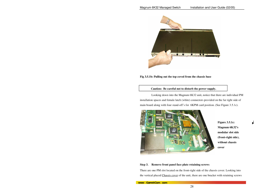
1b Pulling out the top coved from the chassis base
Installing 6KPM Cards in the Magnum 6K32
1d Top View 6KPM retaining screws hold Face Plate
Securely latching up 6KPM Cards into a Magnum 6K32
2g Top View 6KPM Module installed inside a 6K32 Switch
Removing 6KPM Cards
Removing a 6KPM Card
DB-9 Console port connector
Connecting the Console Terminal to Magnum 6K32 Management
Pin Signal Description
Console DB-9 Port
Switching Functionality
Filtering and Forwarding
PWR
Status LEDs
Auto-Cross MDIXAuto-negotiation, for 10/100Mbps RJ-45 ports
ACT
Www . GarrettCom . com
Flow-control, Ieee 802.3x standard
6KP4
’cvr
Magnum 6K32 Managed Switch Port Modules
6KPM Module Description
1b 6KP4-F10ST, 4@10Mb multi-mode FX-ST twist lock Module
Magnum 6KP4
Connectors and configured
As 10Mb Half-duplex by Default for 10Mb fiber
Flstfx is a combo fiber
Copper ports and 2 Single
Mode SC-type connectors. It
Equipped with 4 dual speed
Provides an advantage Through combining copper
Www . GarrettCom . com
Activity FULL/HALF
Port@ 100Mbps Multi-Mode Fiber port
Link
Copper and fiber Small Form Factor
Magnum 6KP8-45MT
Module is a combo module with
Placing more ports on one module
9 6KP8-RJ45 Twisted Pair, 10/100Mb 8-Port
10a 6KP8-45-2LC, 6@ 10/100Mbps RJ-45 and 2@100Mb single-mode
GBIC-SXSC Gigabit fiber1000Mb, multi-mode SC Connector
FX , LC Small-Form-Factor
12 6KM-BLNK
11a GBIC-LXSC Gigabit fiber 1000Mb, multi-mode SC Connector
@ 1000Mb Fiber SC + 2@ 100Mb SC
When Calling for Assistance
Before Calling for Assistance
Return Material Authorization RMA Procedure
No Problem Found
Power Supply Internal -48VDC Option
Appendix B Internal DC Power Supply Options
B1.0 Specifications for Magnum 6K32 SWITCHES, DC Power
Shipping and Packaging Information
Power Supply Internal 125 VDC Option Industrial Applications
B3.0 Applications for DC Powered Switches
B4.1 UL Requirements for DC-powered units
B4.0 Installation
B5.0 Operation
B7.0 Troubleshooting
B6.0 Ordering Information
Appendix C Internal DC Dual-Source Power Option
GND
C4.0 Features and Benefits of the DUAL-SOURCE Design
C5.0 Installation
Example Magnum 6K32R-48VDC
C5.1 UL Requirements
C6.0 Ordering Information
Example Magnum 6K32R-24VDC or Magnum 6K32R-125VDC