Manuals
/
Gateway
/
Computer Equipment
/
Server
Gateway
GT115
manual
Models:
GT115
1
66
71
71
Download
71 pages
21.71 Kb
63
64
65
66
67
68
69
70
Troubleshooting
Specification
Install
Error codes
System Block Diagram
Password
LED indicator
Processor Configuration
Error Symptoms List
Bios Setup
Page 66
Image 66
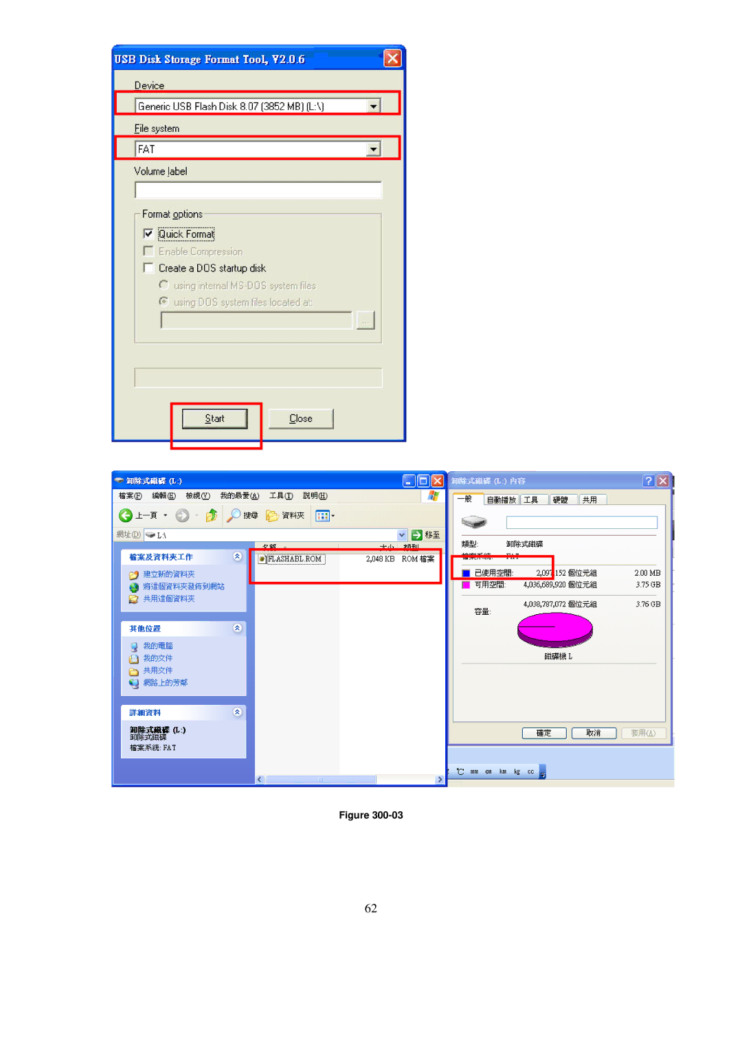
Figure
300-03
62
Page 65
Page 67
Page 66
Image 66
Page 65
Page 67
Contents
Service Guide
Gateway GT115
Revision History
Date Chapter Updates
Preface
Copyright
Conventions
Screen messages
Safety, Care and Regulatory Information
Preventing electrostatic discharge
Server warnings and cautions
Table of Contents
Cable Routing image
Main Menu Advanced Menu
Error Symptoms List
Bios Post error message list PEI Phase DXE Phase
Security Menu
Mechanical Components
Description
Page
System FRU List
Photo Part number
Front Bezel Assembly
Power Supply
System components
Description
System Specifications
Hardware specification
System unit
Processor General processor specifications
Memory
Environmental specification
Mechanical specification
Power supply specification
Page
Appearance of System
Front view
Item Component
Rear view
Icon Component Description
LED indicator
Internal Component
Hard Disk Drive Sequence & LED Description
Switch and LED Indicators Introduction
Front Panel LED Description
LAN Port LED Description
Page
System Block Diagram
SIO
Motherboard Placement and Jumper Setting
Motherboard Component
Connector Icon Description
Code Description
Motherboard Jumper Setting
Installing/Removing system Hardware
Chassis Cover Removal and Installation
Removing the side cover
Removing the tower foot
CPU Installation / Removal
Cooling Fan Installation / Removal
Memory Installation / Removal
Installation step
Memory Suggest Population Table
PCI Expansion Card Installation / Removal
Install the expansion card
Hard Disk Drive Installation / Removal
Power supply installation / Removal
Install a hot-swap power supply module
Cable Routing
Cable Routing image
Suggest Cable
Bios Setup
System Bios
Entering Bios Setup
Bios Setup Primary Menus
Bios Setup Navigation Keys
Main Menu
Parameter Description
Advanced Menu
Processor Configuration
Parameter Description Option
Cpuid
Memory Configuration
Sata Controller Configuration
Achi
PCI Configuration
USB Configuration
Legacy Device Configuration
Console Redirection
VT-UTF8
Page
Power Configuration
Hardware Monitor
Security Menu
Setting a System Password
Changing a System Password
Removing a System Password
Server Menu
System Information
Event Log Configuration
Boot Option Menu
Page
Boot Manager Menu
Exit Menu
Error Symptom Action/FRU Processor / Processor Fan
Troubleshooting
Error Symptoms List
Main board and Memory
CD/DVD-ROM Drive
Video and Monitor
Parallel/Serial Ports
Power Supply
Other Problems
Keyboard
Bios Recovery Instruction
Bios Beep Codes
Bios Beep Codes Table
PEI Beep Codes
Page
Recovery Stage
Bios Post Error Messages List
Bios Post error message list
PEI Phase
DXE Phase
Page
Undetermined Problems
Dimm
Top
Page
Image
Contents