Valve Camshaft
Figure 7
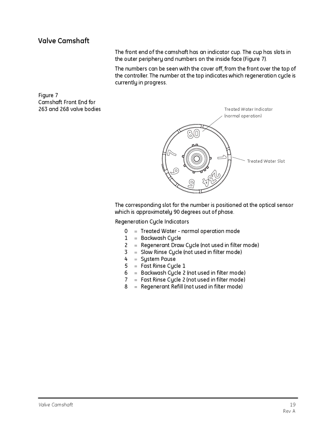
Camshaft Front End for 263 and 268 valve bodies
The front end of the camshaft has an indicator cup. The cup has slots in the outer periphery and numbers on the inside face (Figure 7).
The numbers can be seen with the cover off, from the front over the top of the controller. The number at the top indicates which regeneration cycle is currently in progress.
Treated Water Indicator (normal operation)
Treated Water Slot
The corresponding slot for the number is positioned at the optical sensor which is approximately 90 degrees out of phase.
Regeneration Cycle Indicators
0= Treated Water - normal operation mode
1= Backwash Cycle
2= Regenerant Draw Cycle (not used in filter mode)
3= Slow Rinse Cycle (not used in filter mode)
4= System Pause
5= Fast Rinse Cycle 1
6= Backwash Cycle 2 (not used in filter mode)
7= Fast Rinse Cycle 2 (not used in filter mode)
8= Regenerant Refill (not used in filter mode)
Valve Camshaft | 19 |
| Rev A |