QUICK START GUIDE
Several styles of connector are used to terminate the attached to the end of the fiber cable. The ST and SC connectors shown below, are among the more popular. Ensures that the UR CPU, switch, and cable have compatible connectors.
FIGURE QS–4: Common Fiber Optic Connectors
QS.4.1 Assigning an IP address to the Multilin Switch
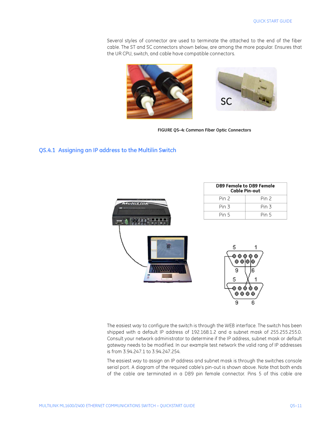
DB9 Female to DB9 Female
Cable
Pin 2 | Pin 2 |
|
|
Pin 3 | Pin 3 |
|
|
Pin 5 | Pin 5 |
|
|
The easiest way to configure the switch is through the WEB interface. The switch has been shipped with a default IP address of 192.168.1.2 and a subnet mask of 255.255.255.0. Consult your network administrator to determine if the IP address, subnet mask or default gateway needs to be modified. In our example test network the valid rang of IP addresses is from 3.94.247.1 to 3.94.247.254.
The easiest way to assign an IP address and subnet mask is through the switches console serial port. A diagram of the required cable’s
MULTILINK ML1600/2400 ETHERNET COMMUNICATIONS SWITCH – QUICKSTART GUIDE |
