GE QS24 UR quick start QS-6

Models: QS24 UR

1 58
Download 58 pages 42.54 Kb
Page 10
Image 10

QUICKSTART GUIDE

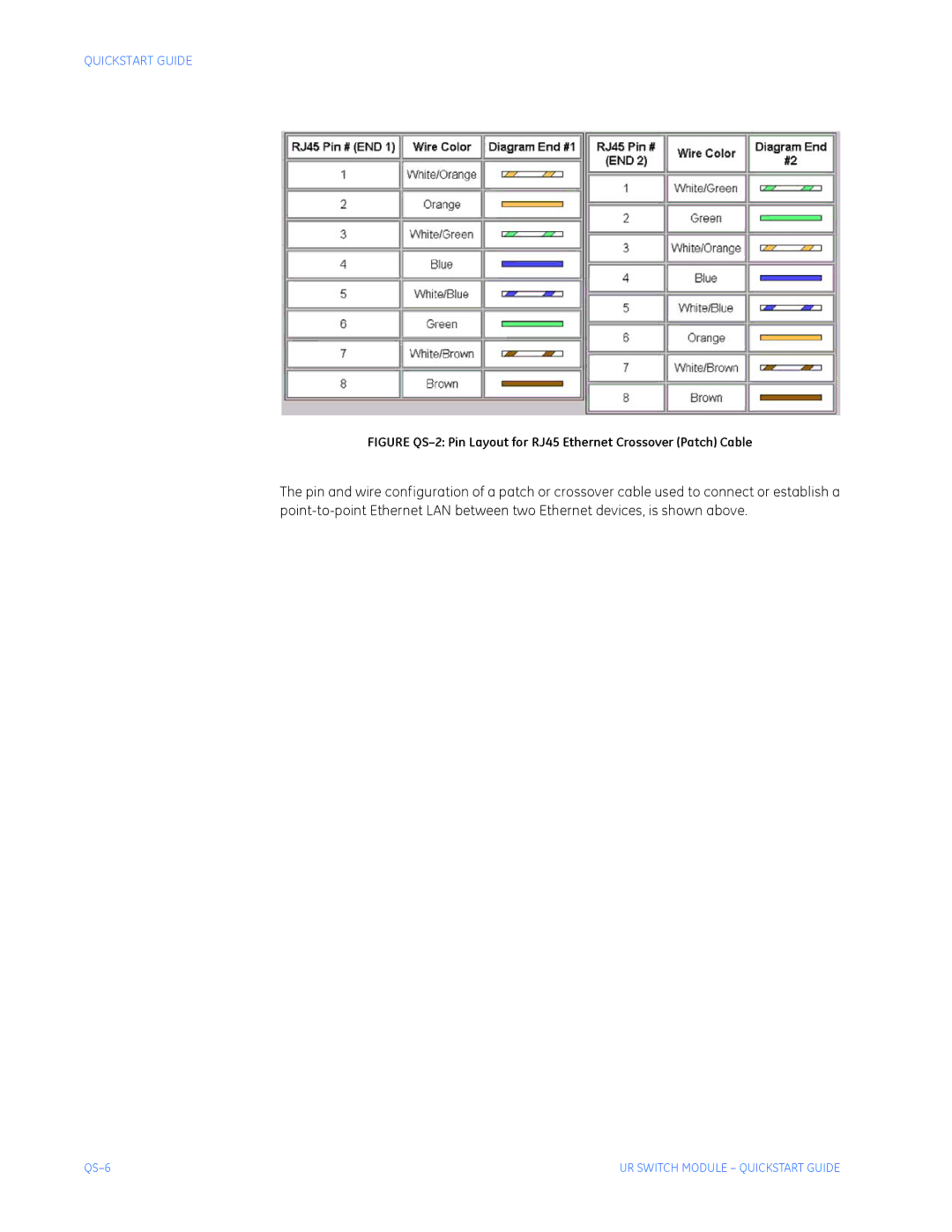
FIGURE QS–2: Pin Layout for RJ45 Ethernet Crossover (Patch) Cable

The pin and wire configuration of a patch or crossover cable used to connect or establish a point-to-point Ethernet LAN between two Ethernet devices, is shown above.

QS–6

UR SWITCH MODULE – QUICKSTART GUIDE

Page 10
Image 10
GE QS24 UR quick start QS-6