QUICKSTART GUIDE
ON = Link Active |
|
| ON = 100Mbps | ||
Flashing LED = Activity |
|
|
|
| OFF = 10 Mbps |
ON = Link Active |
|
|
| ON = Full Duplex | |
Flashing LED = Activity |
|
| |||
|
|
| |||
|
|
|
|
| OFF = Half Duplex |
FIGURE QS–10: LED Functions
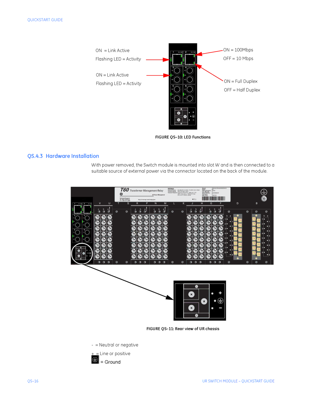
QS.4.3 Hardware Installation
With power removed, the Switch module is mounted into slot W and is then connected to a suitable source of external power via the connector located on the back of the module.
T60 Transformer Management Relay | RATINGS: |
| Model: | T60D00HCHF8AH6AM6BP8BX7A | |
Contact Inputs: | 300V DC Max 10mA | Mods: | 000 | ||
Inst. Manual: | D | ||||
|
| Control Power: | Wiring Diagram: ZZZZZZ | ||
|
| Contact Outputs: Standard Pilot Duty / 250V AC 7.5A | Serial Number: | MAZB98000029 | |
GE Power Management |
| 360V A Resistive / 125V DC Break | Firmware: | D | |
| 4A @ L/R = 40mS / 300W | Mfg. Date: | 1998/01/05 | ||
|
|
|
|
|
|
|
|
|
|
| Technical Support: |
|
|
|
|
|
|
|
| Made in |
|
|
|
|
|
|
|
|
|
|
|
|
|
|
|
|
|
|
| Tel: (905) |
| http://www.ge.com/indsys/pm |
|
| ® |
|
|
|
|
|
|
|
|
|
|
|
|
|
|
| |||
|
|
|
|
|
|
|
| ® |
| Canada |
|
|
|
|
|
|
|
|
|
|
|
|
|
| ||||
|
|
|
|
| Fax: (905) |
|
|
|
|
|
|
|
|
| - M | A | A B 9 | 7 | 0 0 | 0 | 0 | 9 | 9 | - |
|
|
| |
X | W | V | U | T | S | R |
| P | N |
| M | L | K | J | H |
|
| G |
|
|
|
| F |
|
| D | B |
|
| c | b | a |
|
| c | b | a | c | b | a |
| c | b | a |
| c |
|
| b |
| a |
|
|
|
|
|
|
|
|
|
|
|
|
|
|
|
|
|
|
|
|
|
|
|
|
|
|
|
|
|
|
| b | a | b | a |
|
|
|
|
|
|
|
|
|
|
|
|
|
|
|
|
|
|
|
|
|
|
|
|
| 1 |
| 1 |
|
|
|
|
|
|
|
|
|
|
|
|
|
|
|
|
|
|
|
|
|
|
|
|
|
|
| 1 |
| 1 |
|
|
|
|
|
|
|
|
|
|
|
|
|
|
|
|
|
|
|
|
|
|
|
|
| 2 |
| 2 |
|
|
|
|
|
|
|
|
|
|
|
|
|
|
|
|
|
|
|
|
|
|
|
|
|
|
| 2 |
| 2 |
|
|
|
|
|
|
|
|
|
|
|
|
|
|
|
|
|
|
|
|
|
|
|
|
| 3 |
| 3 |
|
|
|
|
|
|
|
|
|
|
|
|
|
|
|
|
|
|
|
|
|
|
|
|
|
|
| 3 |
| 3 |
|
|
|
|
|
|
|
|
|
|
|
|
|
|
|
|
|
|
|
|
|
|
|
|
| 4 |
| 4 |
|
|
|
|
|
|
|
|
|
|
|
|
|
|
|
|
|
|
|
|
|
|
|
|
|
|
| 4 |
| 4 |
|
|
|
|
|
|
|
|
|
|
|
|
|
|
|
|
|
|
|
|
|
|
|
|
| 5 |
| 5 |
|
|
|
|
|
|
|
|
|
|
|
|
|
|
|
|
|
|
|
|
|
|
|
|
|
|
| 5 |
| 5 |
|
|
|
|
|
|
|
|
|
|
|
|
|
|
|
|
|
|
|
|
|
|
|
|
| 6 |
| 6 |
|
|
|
|
|
|
|
|
|
|
|
|
|
|
|
|
|
|
|
|
|
|
|
|
|
|
| 6 |
| 6 |
|
|
|
|
|
|
|
|
|
|
|
|
|
|
|
|
|
|
|
|
|
|
|
|
| 7 |
| 7 |
|
|
|
|
|
|
|
|
|
|
|
|
|
|
|
|
|
|
|
|
|
|
|
|
|
|
| 7 |
| 7 |
|
|
|
|
|
|
|
|
|
|
|
|
|
|
|
|
|
|
|
|
|
|
|
|
| 8 |
| 8 |
|
|
|
|
|
|
|
|
|
|
|
|
|
|
|
|
|
|
|
|
|
|
|
|
|
|
| 8 |
| 8 |
FIGURE QS–11: Rear view of UR chassis
-= Neutral or negative
+ = Line or positive  = Ground
UR SWITCH MODULE – QUICKSTART GUIDE |