Important
E01: High fluid temperature
Causes of E01 Errors
•Thermocouple A or B (361) senses a fluid tempera- ture above 230°F (110°C).
•Fluid temperature sensor (FTS) senses a fluid tem- perature above 230°F (110°C).
•Overtemperature switch (359) senses a fluid tem- perature above 230°F (110°C) and opens. At 190°F (87°C) the switch closes again.
•Thermocouple A or B (361) fails, is damaged, is not touching the heater element (358), or has a poor connection to the temperature control module.
•Overtemperature switch (359) fails in the open posi- tion.
•The temperature control module fails to turn off any heat zone.
•Zone power wires or thermocouples are switched from one zone to another.
•Failed heater element where thermocouple is installed.
•Loose wire
•Jumper wire covered in heat shrink in the wiring har- ness near the single over temperature switch con- nectors on the heater, is loose or incorrectly wired
Checks
Troubleshooting this equipment requires access to parts that may cause electric shock or other serious injury if work is not performed properly. Have a qualified electrician perform all electrical troubleshooting. Be sure to shut off all power to the equipment before repairing.
Check which zone is displaying the E01 error.
1.Check that connector B is firmly plugged into tem- perature control module (see FIG. 6, page 26).
2.Clean and
3.Check connections between the temperature control module and overtemperature switch (359), and
between temperature control module and thermo- couples A and B (361) or FTS (21) [depending on which zone is displaying E01]. See Table 2, page
26. Ensure that all wires are securely connected to connector B.
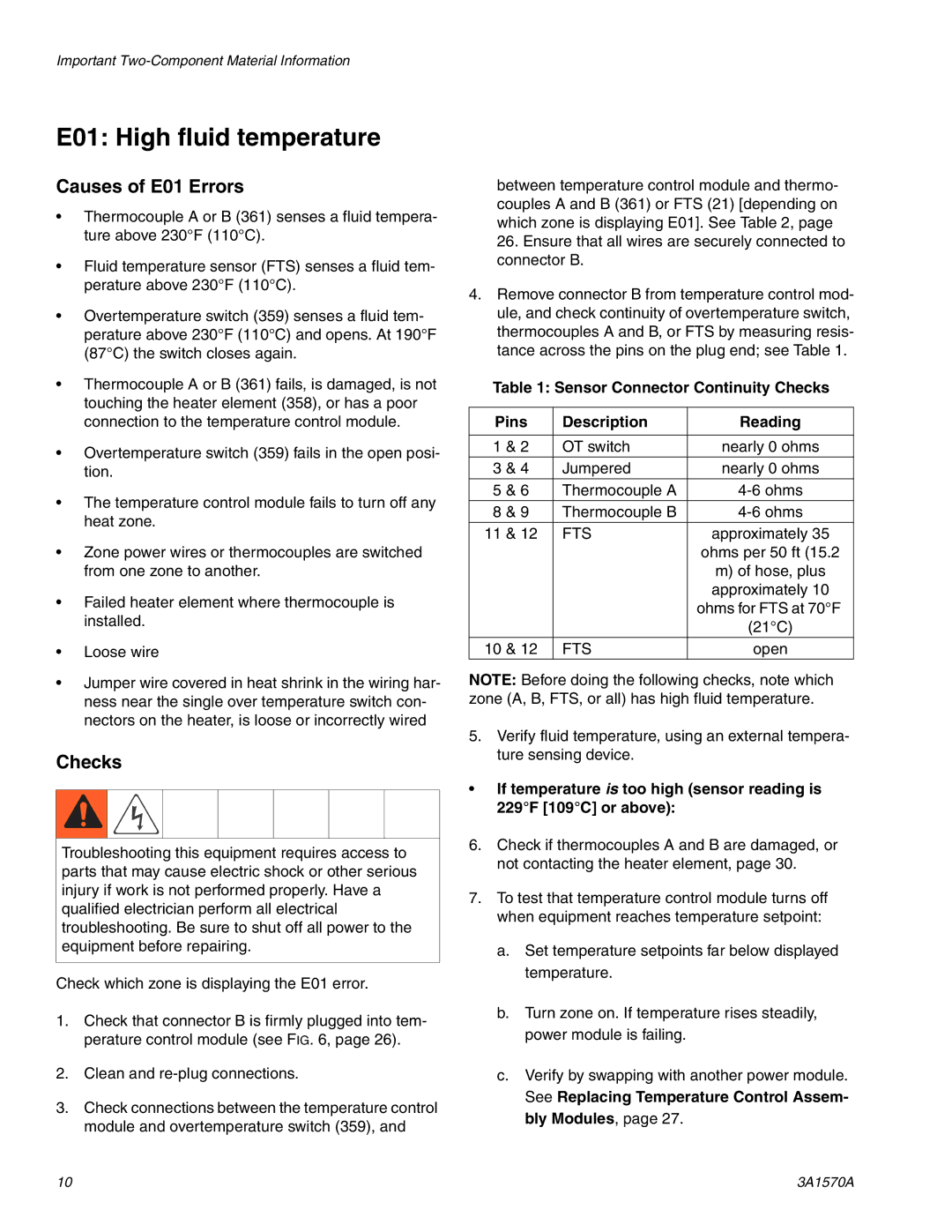
4.Remove connector B from temperature control mod- ule, and check continuity of overtemperature switch, thermocouples A and B, or FTS by measuring resis- tance across the pins on the plug end; see Table 1.
Table 1: Sensor Connector Continuity Checks
Pins | Description | Reading | |
|
|
|
|
1 | & 2 | OT switch | nearly 0 ohms |
3 | & 4 | Jumpered | nearly 0 ohms |
5 | & 6 | Thermocouple A | |
8 | & 9 | Thermocouple B | |
11 | & 12 | FTS | approximately 35 |
|
|
| ohms per 50 ft (15.2 |
|
|
| m) of hose, plus |
|
|
| approximately 10 |
|
|
| ohms for FTS at 70°F |
|
|
| (21°C) |
10 | & 12 | FTS | open |
NOTE: Before doing the following checks, note which zone (A, B, FTS, or all) has high fluid temperature.
5.Verify fluid temperature, using an external tempera- ture sensing device.
•If temperature is too high (sensor reading is 229°F [109°C] or above):
6.Check if thermocouples A and B are damaged, or not contacting the heater element, page 30.
7.To test that temperature control module turns off when equipment reaches temperature setpoint:
a.Set temperature setpoints far below displayed temperature.
b.Turn zone on. If temperature rises steadily, power module is failing.
c.Verify by swapping with another power module. See Replacing Temperature Control Assem- bly Modules, page 27.
10 | 3A1570A |
