Parts
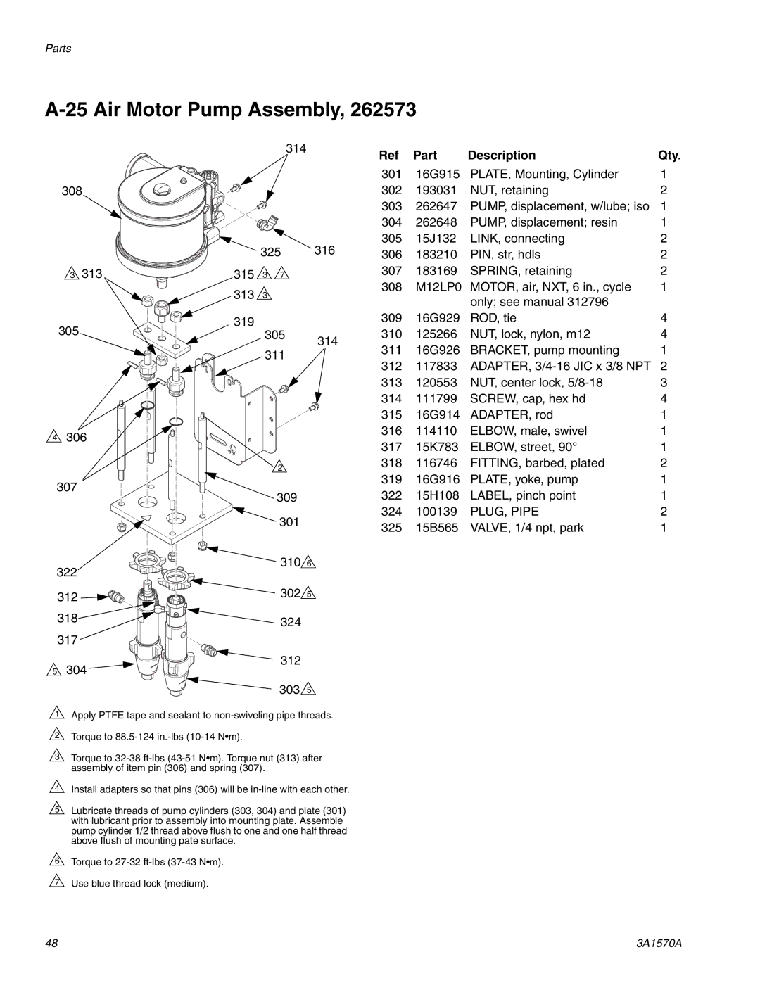
A-25 Air Motor Pump Assembly, 262573
308
![]() 3 313
3 313
305
![]() 4 306
4 306
307
314
325 316
315 ![]() 3
3 ![]() 7
7
313![]() 3
3
319
305314
![]() 2
2
![]() 309 301
309 301
Ref | Part | Description | Qty. |
301 | 16G915 | PLATE, Mounting, Cylinder | 1 |
302 | 193031 | NUT, retaining | 2 |
303 | 262647 | PUMP, displacement, w/lube; iso | 1 |
304 | 262648 | PUMP, displacement; resin | 1 |
305 | 15J132 | LINK, connecting | 2 |
306 | 183210 | PIN, str, hdls | 2 |
307 | 183169 | SPRING, retaining | 2 |
308 | M12LP0 | MOTOR, air, NXT, 6 in., cycle | 1 |
|
| only; see manual 312796 |
|
309 | 16G929 | ROD, tie | 4 |
310 | 125266 | NUT, lock, nylon, m12 | 4 |
311 | 16G926 | BRACKET, pump mounting | 1 |
312 | 117833 | ADAPTER, | 2 |
313 | 120553 | NUT, center lock, | 3 |
314 | 111799 | SCREW, cap, hex hd | 4 |
315 | 16G914 | ADAPTER, rod | 1 |
316 | 114110 | ELBOW, male, swivel | 1 |
317 | 15K783 | ELBOW, street, 90° | 1 |
318 | 116746 | FITTING, barbed, plated | 2 |
319 | 16G916 | PLATE, yoke, pump | 1 |
322 | 15H108 | LABEL, pinch point | 1 |
324 | 100139 | PLUG, PIPE | 2 |
325 | 15B565 | VALVE, 1/4 npt, park | 1 |
322 | 310 6 | |
| ||
312 | 302 5 | |
| ||
318 | 324 | |
|
| |
317 |
| |
5 | 304 | 312 |
| ||
|
| 303 5 |
1 | Apply PTFE tape and sealant to | |
2 | Torque to |
|
3 | Torque to | |
| assembly of item pin (306) and spring (307). |
|
4 | Install adapters so that pins (306) will be | |
5 | Lubricate threads of pump cylinders (303, 304) and plate (301) | |
| with lubricant prior to assembly into mounting plate. Assemble | |
| pump cylinder 1/2 thread above flush to one and one half thread | |
| above flush of mounting pate surface. |
|
6 | Torque to |
|
7 | Use blue thread lock (medium). |
|
48 | 3A1570A |