Transformer Primary Check
1. Turn main power OFF | . |
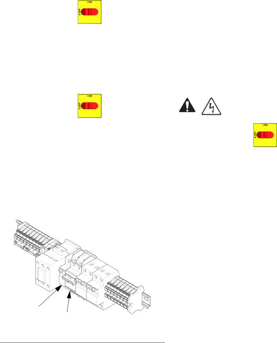
2.Locate the two smaller (10 AWG) wires coming out of transformer. Trace these wires back to contactor and circuit breaker (911). Use an ohmmeter to test for continuity between two wires; there should be continuity.
Repair
3.To verify transformer voltage, turn on hose zone. Measure voltage from
Model | Secondary Voltage |
|
|
|
|
310 ft. | 90 Vac* |
|
|
210 ft. | 62 Vac* |
|
|
* For 230 Vac line voltage.
Transformer Secondary Check | Replace Transformer | |||||||
1. Turn main power OFF | . |
|
|
|
|
|
|
|
|
|
|
|
|
|
| ||
|
|
|
|
|
|
|
|
|
2.Locate the two larger (6 AWG) wires coming out of transformer. Trace these wires back to large green connector under hose control module and circuit breaker (909). Use an ohmmeter to test for continu- ity between two wires; there should be continuity.
If you are not sure which wire in green plug under hose module connects to transformer, test both wires. One wire should have continuity with the other transformer wire in breaker (909) and the other wire should not.
909
911
ti17999a
FIG. 11: Circuit Breaker Module
1. Turn main power OFF | . Disconnect power |
supply.
2.Open Reactor cabinet.
3.Remove bolts holding transformer to cabinet floor. Slide transformer forward.
4.Disconnect the transformer wires; see Reactor
5.Remove transformer from cabinet.
6.Install new transformer in reverse order.
3A1570A | 33 |
