Knife Setting Jig Method: Both tables are low- ered to fit the jig on the cutterhead, as shown in Figure 43, and the knife heights are set to just touch the middle pad of the jig.
The knife setting jig makes it easy to ensure that the knives project out of the cutterhead evenly. After using the knife setting jig to set the knives, you have to
Figure 43. Using knife setting jig to set knife
height.
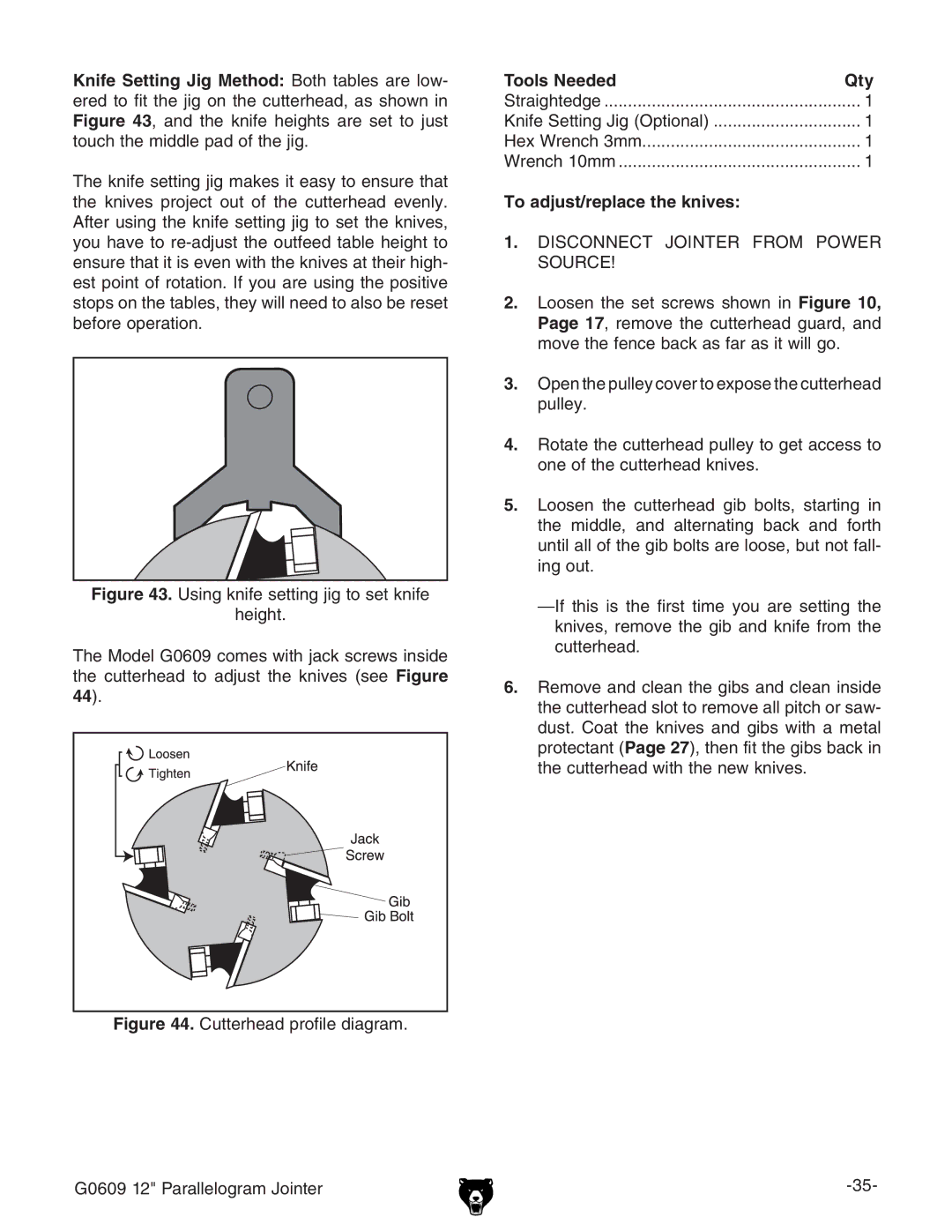
The Model G0609 comes with jack screws inside the cutterhead to adjust the knives (see Figure 44).
Figure 44. Cutterhead profile diagram.
Tools Needed | Qty |
Straightedge | 1 |
Knife Setting Jig (Optional) | 1 |
Hex Wrench 3mm | 1 |
Wrench 10mm | 1 |
To adjust/replace the knives: |
|
1.DISCONNECT JOINTER FROM POWER SOURCE!
2.Loosen the set screws shown in Figure 10, Page 17, remove the cutterhead guard, and move the fence back as far as it will go.
3.Open the pulley cover to expose the cutterhead pulley.
4.Rotate the cutterhead pulley to get access to one of the cutterhead knives.
5.Loosen the cutterhead gib bolts, starting in the middle, and alternating back and forth until all of the gib bolts are loose, but not fall- ing out.
6.Remove and clean the gibs and clean inside the cutterhead slot to remove all pitch or saw- dust. Coat the knives and gibs with a metal protectant (Page 27), then fit the gibs back in the cutterhead with the new knives.
G0609 12" Parallelogram Jointer |