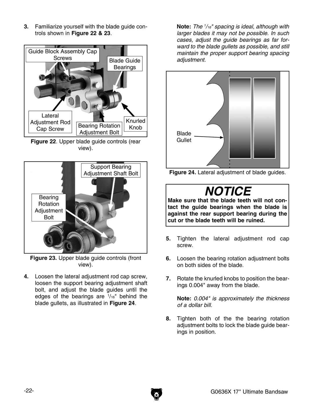
3.Familiarize yourself with the blade guide con- trols shown in Figure 22 & 23.
Guide Block Assembly Cap |
| ||
Screws | Blade Guide | ||
| |||
| Bearings | ||
Lateral |
| Knurled | |
Adjustment Rod | Bearing Rotation | ||
Cap Screw | Knob | ||
Adjustment Bolt | |||
|
| ||
Figure 22. Upper blade guide controls (rear
view).
Support Bearing |
Adjustment Shaft Bolt |
Bearing |
Rotation |
Adjustment |
Bolt |
Figure 23. Upper blade guide controls (front
view).
4.Loosen the lateral adjustment rod cap screw, loosen the support bearing adjustment shaft bolt, and adjust the blade guides until the edges of the bearings are 1/16" behind the blade gullets, as illustrated in Figure 24.
Note: The 1/16" spacing is ideal, although with larger blades it may not be possible. In such cases, adjust the guide bearings as far for- ward to the blade gullets as possible, and still maintain the proper support bearing spacing adjustment.
Blade
Gullet 
Figure 24. Lateral adjustment of blade guides.
NOTICE
Make sure that the blade teeth will not con- tact the guide bearings when the blade is against the rear support bearing during the cut or the blade teeth will be ruined.
5.Tighten the lateral adjustment rod cap screw.
6.Loosen the bearing rotation adjustment bolts on both sides of the blade.
7.Rotate the knurled knobs to position the bear- ings 0.004" away from the blade.
Note: 0.004" is approximately the thickness of a dollar bill.
8.Tighten both of the the bearing rotation adjustment bolts to lock the blade guide bear- ings in position.
G0636X 17" Ultimate Bandsaw |