G0705 Wiring Diagram (Continued)
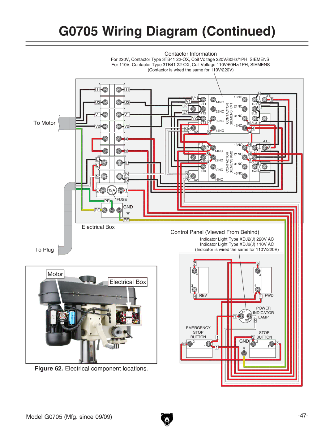
Contactor Information
For 220V, Contactor Type 3TB41
To Motor
To Plug
U1 |
| U1 |
|
|
|
|
|
|
| N |
|
|
|
|
| V1 |
|
|
| 13NO |
| A1 | |
|
|
|
|
|
|
|
|
| |||
U2 |
| U2 | V1 |
| 14NO |
| 1L1 N | 6 | |||
|
|
|
|
| |||||||
|
| 2T1 | CONTACTOR SIEMENS KM1 |
|
| ||||||
|
|
| U2 |
|
|
| 21NC |
| L |
| |
V1 |
| V1 | U2 |
| 4T2 | 22NC | 31NC | 3L2 |
|
| |
|
| V2 |
|
|
|
|
| ||||
|
|
|
| 6T3 7 | 32NC |
| 8 5L3 L |
| |||
|
|
|
|
|
|
| |||||
V2 |
| V2 |
|
|
| 43NO |
| ||||
| N |
|
|
|
| 4 |
|
| |||
|
|
|
|
| 44NO |
|
|
|
| ||
|
|
| A2 | 5 |
|
| 4 |
|
| ||
|
|
|
|
|
|
|
| ||||
|
|
|
|
|
|
|
|
| |||
|
| 4 |
|
|
|
|
|
|
|
| A1 |
|
|
|
|
| 2T1 |
|
| 13NO | 4 |
| |
|
|
|
|
|
|
|
| 8 | |||
|
| 3 |
|
| 7 | 14NO |
|
|
| L | |
|
|
|
| 5 | CONTACTOR SIEMENS KM2 | 21NC | 4 1L1 |
| |||
L |
| L |
|
| 4T2 5 | 22NC | 31NC | 6 3L2 L |
| ||
L |
|
|
|
|
| ||||||
|
|
|
|
|
|
|
|
|
| ||
|
| N | N |
| 6T3 | 32NC | 43NO | 5L3 L |
| ||
|
|
|
|
|
|
|
| ||||
N |
|
|
|
|
|
|
|
| |||
| N | N | A2 |
| 44NO |
|
|
|
|
| |
|
|
|
|
|
|
|
| ||||
L | 12A | 1 |
|
|
|
|
|
|
|
|
|
| PE | FUSE |
|
|
|
|
|
|
|
|
|
|
|
|
|
|
|
|
|
|
|
| |
PE |
| GND |
|
|
|
|
|
|
|
|
|
|
|
|
|
|
|
|
|
|
|
| |
|
| PE |
|
|
|
|
|
|
|
|
|
Electrical Box |
Control Panel (Viewed From Behind) |
Indicator Light Type XDJ2(J) 220V AC |
Indicator Light Type XDJ2(J) 110V AC |
(Indicator is wired the same for 110V/220V) |
Motor
Electrical Box
Figure 62. Electrical component locations.
7 |
| 5 |
|
4 |
| 3 |
|
3 |
| 4 |
|
4 | REV | 4 | FWD |
X1 | POWER |
INDICATOR | |
1 | N LAMP |
X2 |
| EMERGENCY |
|
|
|
|
| STOP |
|
| STOP |
|
| BUTTON | 1 | GND | 3 BUTTON |
|
2 | 2 |
| 2 | 2 | |
1 | 1 |
| 1 | ||
|
|
|
Model G0705 (Mfg. since 09/09) |
