Lifting & Placing
HEAVy LIFT!
Straining or crushing injury may occur from improperly lifting machine or some of its parts. To reduce this risk, get help from other people and use a fork lift (or other lifting equipment) rated for weight of this machine.
Power lifting equipment (refer to Page 16) and at least two other people are required to lift and place the mill.
To lift and move the mill:
1.remove the crate from the shipping pallet, then move the mill, while it is still on the pal- let, to the installation location.
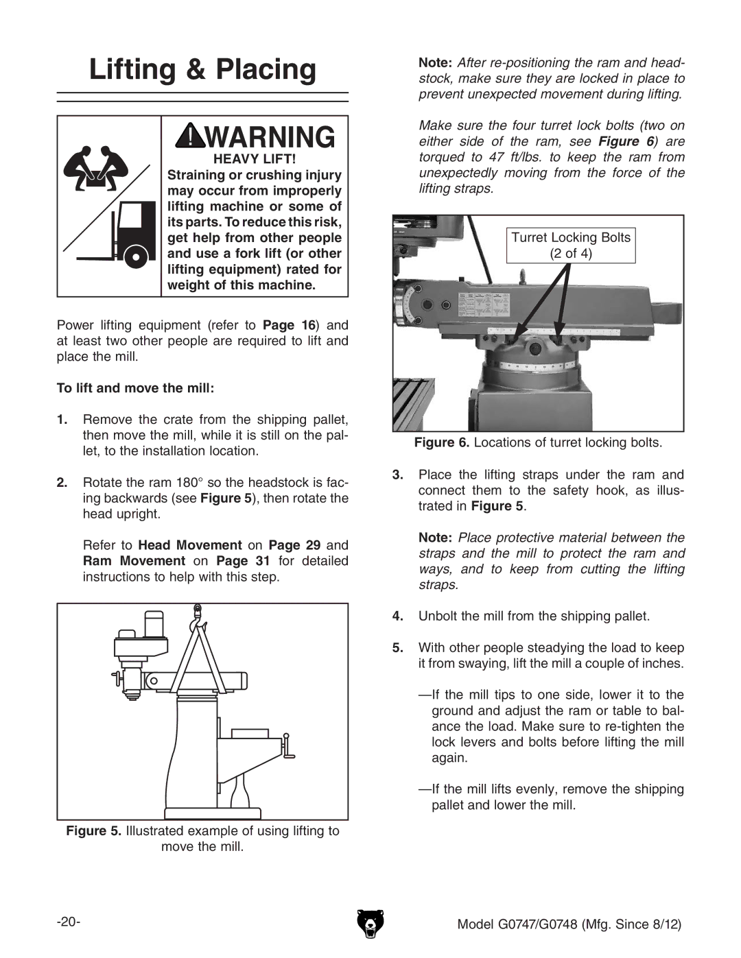
2.rotate the ram 180° so the headstock is fac- ing backwards (see Figure 5), then rotate the head upright.
Refer to Head Movement on Page 29 and Ram Movement on Page 31 for detailed instructions to help with this step.
Figure 5. Illustrated example of using lifting to
move the mill.
Note: After
Make sure the four turret lock bolts (two on either side of the ram, see Figure 6) are torqued to 47 ft/lbs. to keep the ram from unexpectedly moving from the force of the lifting straps.
Turret Locking Bolts
(2 of 4)
Figure 6. Locations of turret locking bolts.
3.place the lifting straps under the ram and connect them to the safety hook, as illus- trated in Figure 5.
Note: Place protective material between the straps and the mill to protect the ram and ways, and to keep from cutting the lifting straps.