Control Panel
A
B
C
F
D | G |
|
H
I
E
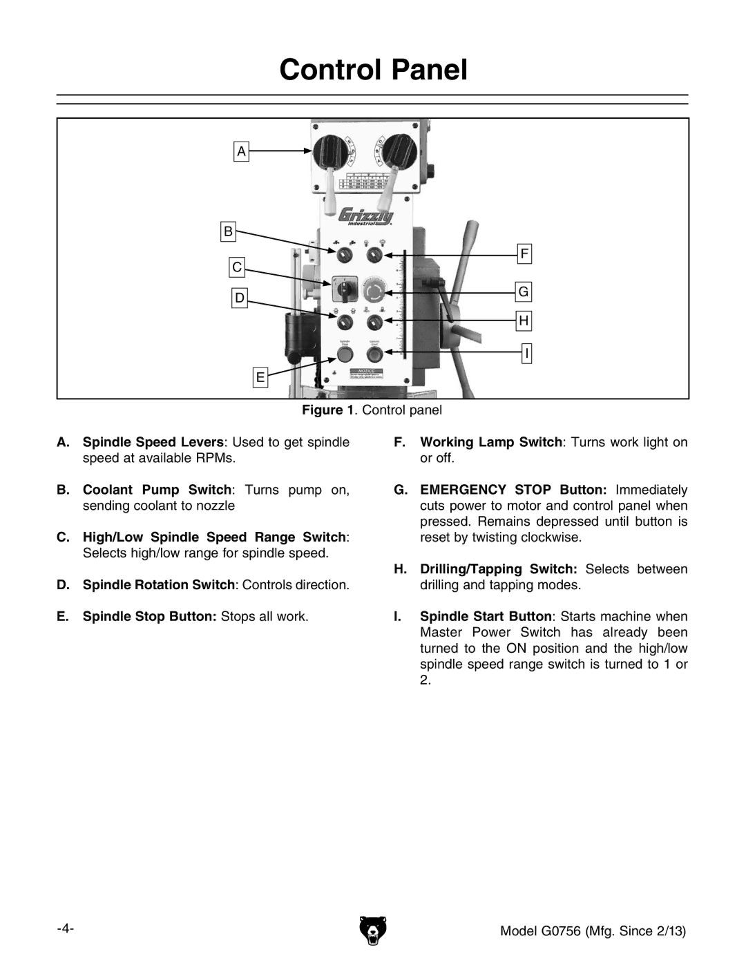
Figure 1. Control panel
A.Spindle Speed Levers: Used to get spindle speed at available RPMs.
B.Coolant Pump Switch: Turns pump on, sending coolant to nozzle
C.High/Low Spindle Speed Range Switch: Selects high/low range for spindle speed.
D.Spindle Rotation Switch: Controls direction.
E.Spindle Stop Button: Stops all work.
F.Working Lamp Switch: Turns work light on or off.
G.EMERGENCY STOP Button: Immediately cuts power to motor and control panel when pressed. Remains depressed until button is reset by twisting clockwise.
H.Drilling/Tapping Switch: Selects between drilling and tapping modes.
I.Spindle Start Button: Starts machine when Master Power Switch has already been turned to the ON position and the high/low spindle speed range switch is turned to 1 or 2.
Model G0756 (Mfg. Since 2/13) |
