Identification
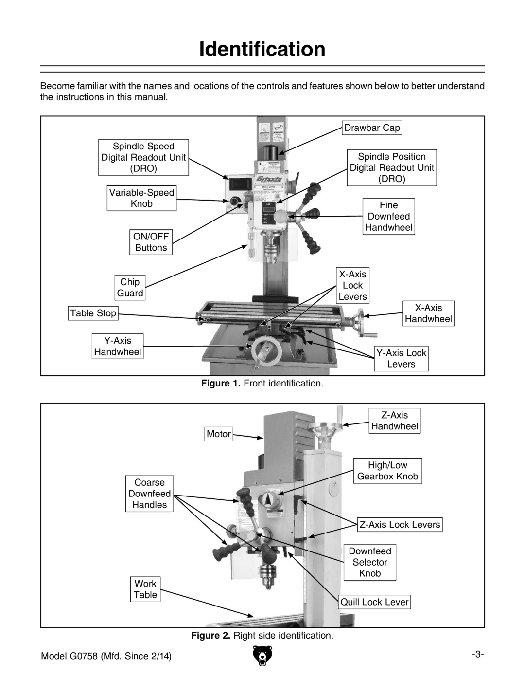
Become familiar with the names and locations of the controls and features shown below to better understand the instructions in this manual.
| Drawbar Cap | |
Spindle Speed | Spindle Position | |
Digital Readout Unit | ||
(DRO) | Digital Readout Unit | |
| (DRO) | |
| ||
Knob | Fine | |
| Downfeed | |
ON/OFF | Handwheel | |
| ||
Buttons |
| |
Chip | ||
Lock | ||
Guard | ||
Levers | ||
| ||
Table Stop | ||
Handwheel | ||
| ||
| ||
Handwheel | ||
| Levers |
Figure 1. Front identification.
Motor
Coarse
Downfeed
Handles
Work
Table ![]()
Z-Axis
Handwheel
High/Low
Gearbox Knob
Z-Axis Lock Levers
Downfeed
Selector
Knob
Quill Lock Lever
Figure 2. Right side identification.
Model G0758 (Mfd. Since 2/14) |
