Apron Threading Controls
The half nut lever engages the carriage with the leadscrew, which moves the carriage and cutting tool along the length of the workpiece for thread- ing operations (see Figure 65).
Half Nut |
| Thread Dial |
Lever |
|
|
|
|
|
 Disengaged
Halfnut
Lever
Engaged
Figure 65. Apron threading controls.
Thread Dial
The numbers on the thread dial (Figure 65) are used with the thread dial chart to show when to engage the half nut during inch threading.
Note: The thread dial is not used for metric threading. You must leave the half nut engaged from the beginning until the turning is complete for this type of operation.
When threading, we recommend using the slowest speed possible and avoiding deep cuts, so you are able to disengage the half nut when required to prevent a carriage crash!
When the first cutting pass is complete, the opera- tor disengages the carriage from the leadscrew using the half nut lever. The operator returns the carriage for the next pass and
Model G0765 (Mfd. Since 12/13)
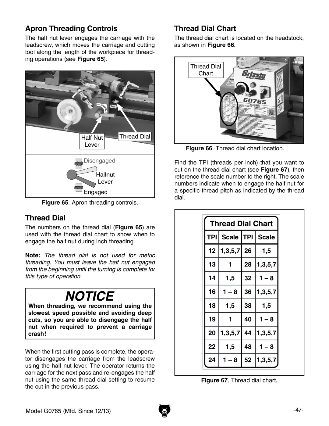
Thread Dial Chart
The thread dial chart is located on the headstock, as shown in Figure 66.
Thread Dial
Chart
Figure 66. Thread dial chart location.
Find the TPI (threads per inch) that you want to cut on the thread dial chart (see Figure 67), then reference the scale number to the right. The scale numbers indicate when to engage the half nut for a specific thread pitch as indicated by the thread dial.
Thread Dial Chart
TPI | Scale | TPI | Scale |
|
|
|
|
12 | 1,3,5,7 | 26 | 1,5 |
|
|
|
|
13 | 1 | 28 | 1,3,5,7 |
|
|
|
|
14 | 1,5 | 32 | 1 – 8 |
|
|
|
|
16 | 1 – 8 | 36 | 1,3,5,7 |
|
|
|
|
18 | 1,5 | 38 | 1,5 |
|
|
|
|
19 | 1 | 40 | 1 – 8 |
|
|
|
|
20 | 1,3,5,7 | 44 | 1,3,5,7 |
|
|
|
|
22 | 1,5 | 48 | 1 – 8 |
|
|
|
|
24 | 1 – 8 | 52 | 1,3,5,7 |
|
|
|
|
|
|
|
|