Steady Rest
The steady rest supports long shafts and can be mounted anywhere along the length of the bed- way.
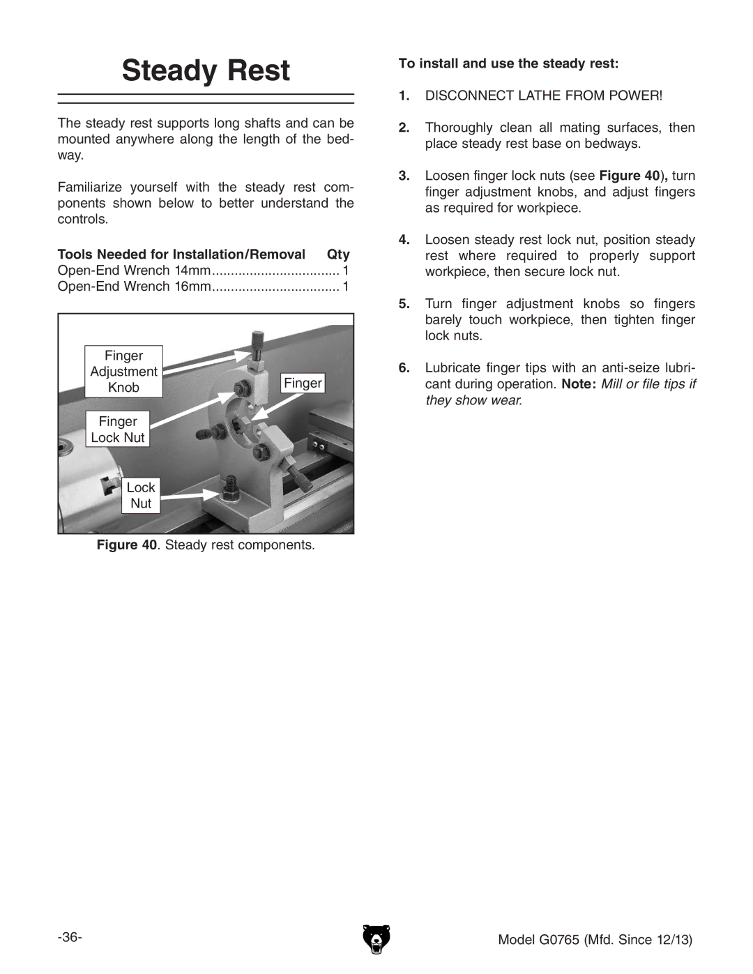
Familiarize yourself with the steady rest com- ponents shown below to better understand the controls.
Tools Needed for Installation/Removal | Qty |
1 | |
1 |
Finger |
| |
Adjustment | Finger | |
Knob | ||
| ||
Finger |
| |
Lock Nut |
| |
Lock |
| |
Nut |
|
Figure 40. Steady rest components.
To install and use the steady rest:
1.DISCONNECT LATHE FROM POWER!
2.Thoroughly clean all mating surfaces, then place steady rest base on bedways.
3.Loosen finger lock nuts (see Figure 40), turn finger adjustment knobs, and adjust fingers as required for workpiece.
4.Loosen steady rest lock nut, position steady rest where required to properly support workpiece, then secure lock nut.
5.Turn finger adjustment knobs so fingers barely touch workpiece, then tighten finger lock nuts.
6.Lubricate finger tips with an
Model G0765 (Mfd. Since 12/13) |