Identification
Become familiar with the names and locations of the controls and features shown below to better understand the instructions in this manual.
|
|
|
|
|
|
| C | D |
A |
| B | F |
|
|
|
|
|
|
| E |
|
| I |
|
| |
|
|
| G | H |
|
| ||
|
|
|
| J |
|
| ||
W |
|
|
|
|
|
| K | |
V |
|
|
|
|
|
|
|
|
|
|
|
|
|
|
|
| L |
U | T |
| S |
|
|
|
|
|
|
|
|
|
| P | O |
|
|
|
|
| R | Q | N |
|
| |
|
|
|
| M |
| |||
|
|
|
|
|
|
|
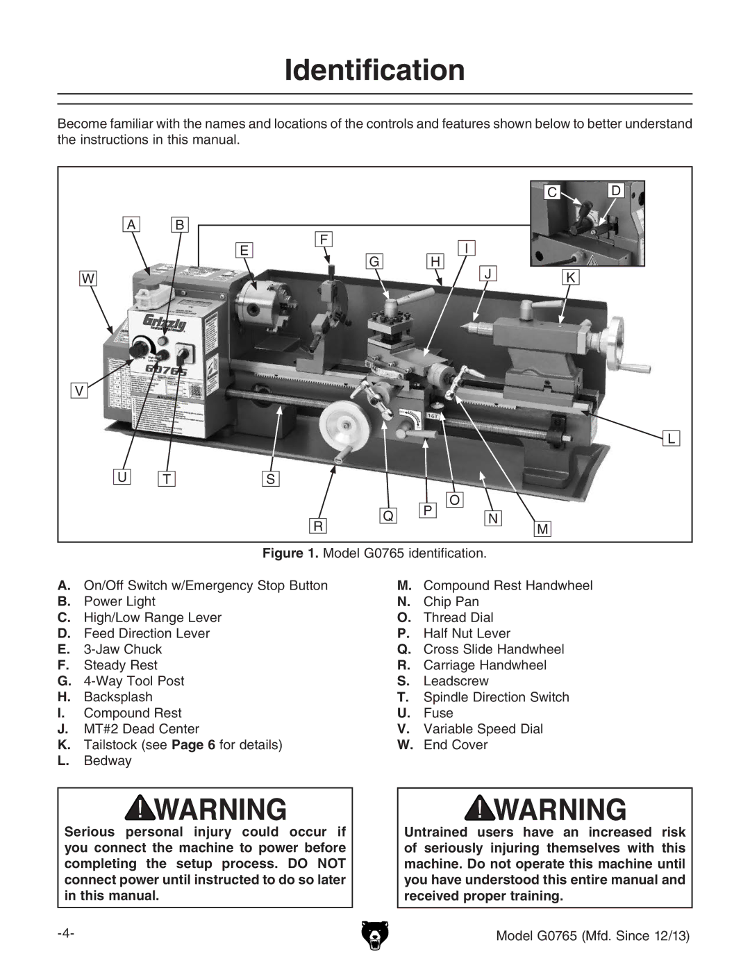
Figure 1. Model G0765 identification.
A.On/Off Switch w/Emergency Stop Button
B.Power Light
C.High/Low Range Lever
D.Feed Direction Lever
E.3-Jaw Chuck
F.Steady Rest
G.4-Way Tool Post
H.Backsplash
I.Compound Rest
J.MT#2 Dead Center
K.Tailstock (see Page 6 for details)
L.Bedway
Serious personal injury could occur if you connect the machine to power before completing the setup process. DO NOT connect power until instructed to do so later in this manual.
M.Compound Rest Handwheel
N.Chip Pan
O.Thread Dial
P.Half Nut Lever
Q.Cross Slide Handwheel
R.Carriage Handwheel
S.Leadscrew
T.Spindle Direction Switch
U.Fuse
V.Variable Speed Dial
W.End Cover
Untrained users have an increased risk of seriously injuring themselves with this machine. Do not operate this machine until you have understood this entire manual and received proper training.
Model G0765 (Mfd. Since 12/13) |