INSTALLATION

Diagram 8

3)To install the Round Support Box/Wall Thim- ble in a fl at ceiling, cut a 10 inch square hole in the ceiling centred on the hole drilled in Step 2. Frame the hole as shown in diagram 9.

Diagram 9

4)Assemble the desired lengths of black pipe and elbows necessary to reach from the appliance adapter up though the Round Support Box. Insure that all pipes and elbow connections are in the fully twist-locked position and sealed.

Diagram 10: The upper half of the fl ashing is installed under the roofi ng material and not nailed down until the chimney is installed. This allows for small adjustments.

Note: If an offset is necessary in the attic to avoid obstructions, it is important to support the vent pipe every 3 feet, to avoid excessive stress on the elbows, and possible separation. Wall straps are available for this purpose. See diagram 5.

Galvanizedpipeandelbowsmaybeutilized in the attic as well as above the roofl ine. The galvanized fi nish is desirable above the roofl ine due to its higher corrosion resistance.

Continue to add pipe sections through the

ashing until the height of the vent cap meets the minimum height requirements specifi ed in diagram 11 or local codes. Note that for steep roof pitches, the vertical height must be increased. A poor draft, or down drafting can result from high wind conditions near big trees or adjoining roof lines, in these cases, increasing the vent height may solve the problem.

7)Ensure vent is vertical and secure the base of the fl ashing to the roof with roofi ng rails, slide storm collar over the pipe section and seal with a mastic.

8)Install the vertical termination cap by twist locking it.

Notes:

a)For multistorey vertical installations, a Ceiling Fire stop (Part # 963) is required at the second floor, and any subsequent fl oor. Diagram 12. The opening should be framed to 10 " x 10" inside dimen- sions, in the same manner as shown in diagram 9.

b)Any occupied areas above the first floor, including closets and storage spaces, through which the vertical vent passes, must be enclosed.

Diagram 12

NOTE: For best results and optimum per- formancewitheachapprovedventing system, it is highly recommended to apply“Mill-Pac”sealant(supplied)to every inner pipe connection. Failure to do so may result in drafting or performance issues not covered under warranty. Silicone (red RTV) is optional.

5)Cut a hole in the roof centred on the small drilled hole placed in the roof in Step 2. The hole should be of suffi cient size to meet the minimum requirements for clearance to combustibles of 1-1/4". Slip the fl ashing under the shingles (shingles should overlap half the fl ashing) as per diagram 10.

6)Continue to assemble pipe lengths.

Diagram 11

Roof Pitch

Minimum Vent Height


Feet

Meters

fl at to 7/12

2

0.61

over 7/12 to 8/12

2

0.61

over 8/12 to 9/12

2

0.61

over 9/12 to 10/12

2.5

0.76

over 10/12 to 11/12

3.25

0.99

over 11/12 to 12/12

4

1.22

over 12/12 to 14/12

5

1.52

over 14/12 to 16/12

6

1.83

over 16/12 to 18/12

7

2.13

over 18/12 to 20/12

7.5

2.29

over 20/12 to 21/12

8

2.44


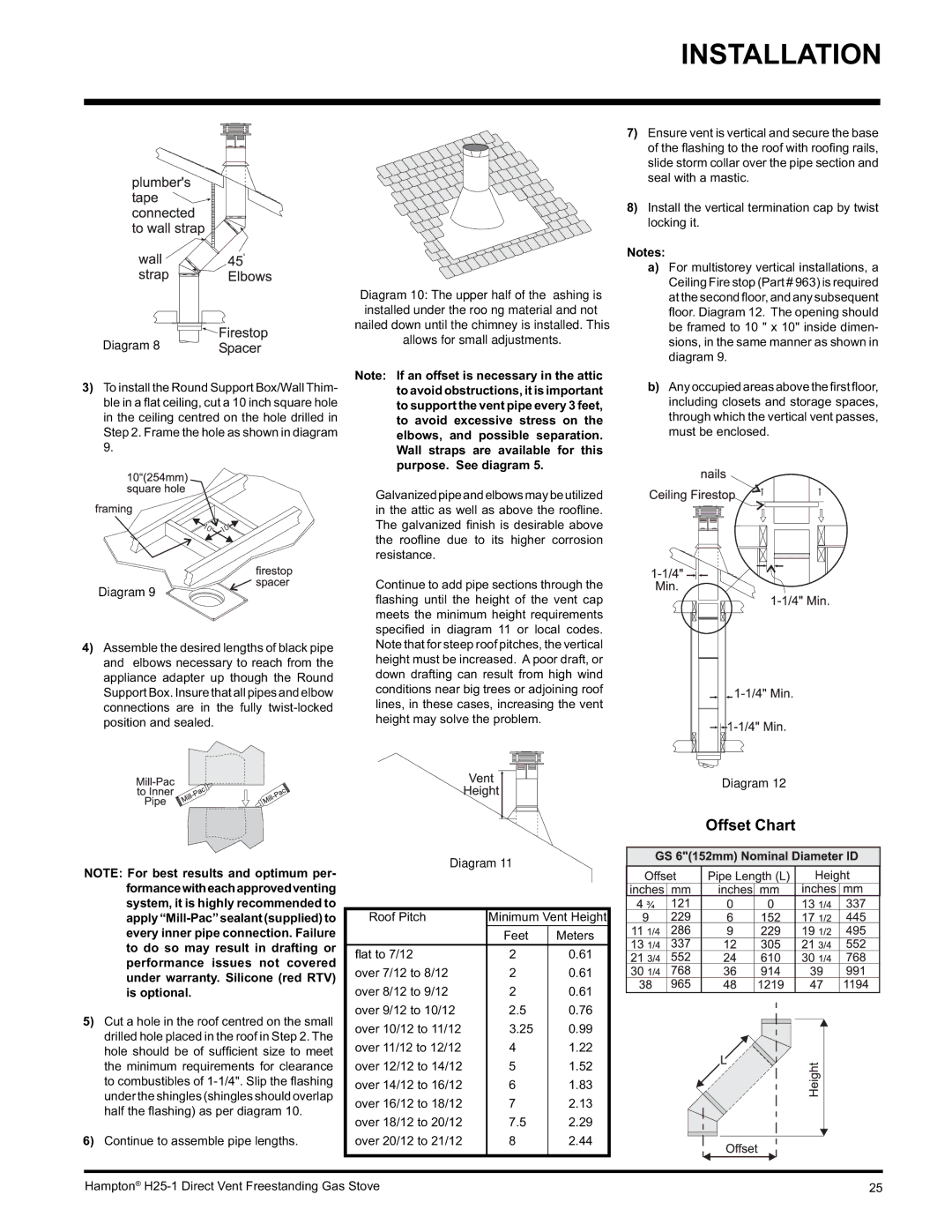
Offset Chart

Hampton® H25-1 Direct Vent Freestanding Gas Stove

25

Page 25
Image 25
Hampton Direct H25-LP1 Propane, H25-NG1, H25-LP1 installation manual Offset Chart

H25-LP1 Propane, H25-NG1, H25-LP1 specifications

Hampton Direct H25 series, which includes the H25-NG1, H25-LP1, and H25-LP1 Propane models, represents an innovative lineup of gas stoves designed to deliver efficient heating with modern aesthetics. These stoves are perfect for residential and recreational use, providing an economical solution for space heating with exceptional comfort and performance.

One of the standout features of the H25 series is its multi-fuel capability. The H25-NG1 operates on natural gas, while the H25-LP1 and H25-LP1 Propane models utilize liquid propane. This flexibility allows homeowners to select the model that best fits their energy source availability. Each of these units is designed with a powerful heat output, ensuring efficient coverage of living spaces, making them suitable for open floor plan homes and larger areas.

The stoves incorporate advanced combustion technologies, which enable them to burn fuel more efficiently. This leads to less environmental impact, lower emissions, and improved energy use. The H25 series devices utilize a patented firebox design that maximizes heat retention, resulting in extended heating times and better temperature control. Users can expect significant energy savings, as the stoves are engineered to extract more heat from the fuel consumed.

Aesthetically, the H25 series offers an elegant design that adds a contemporary touch to any room. The clean lines and modern finish allow the units to blend seamlessly with various interior styles. Moreover, the units feature large viewing windows that provide a mesmerizing flame display, creating a cozy and inviting atmosphere.

Ease of use is another critical characteristic. Each model comes with user-friendly controls that allow homeowners to adjust the flame height and heat output easily. Additionally, the units have safety features, including automatic shut-off valves, ensuring peace of mind.

The H25 series is engineered for durability, featuring high-quality materials that withstand the test of time. Whether selected for a primary residence or a cozy retreat, the Hampton Direct H25-NG1, H25-LP1, and H25-LP1 Propane models offer an outstanding combination of efficiency, design, and performance that aligns with today’s heating needs.