To Assemble And Attach The Bevel And Height Handles To The Base:
1.Insert one Screw (part #6G) each through a Bevel Handle and Height Handle (part #5G). Tighten each Screw into a Hand Wheel Assembly (part #4G). Then, attach an End Cap (part #7G) to each of the two Handles.
(See Figures B, M, and Assy. Diagram G.)
2.Align one Handle Assembly (part #4G) with the Height Adjustment Rod (part
3.Align the remaining Handle Assembly (part #4G) with the Threaded Rod (part
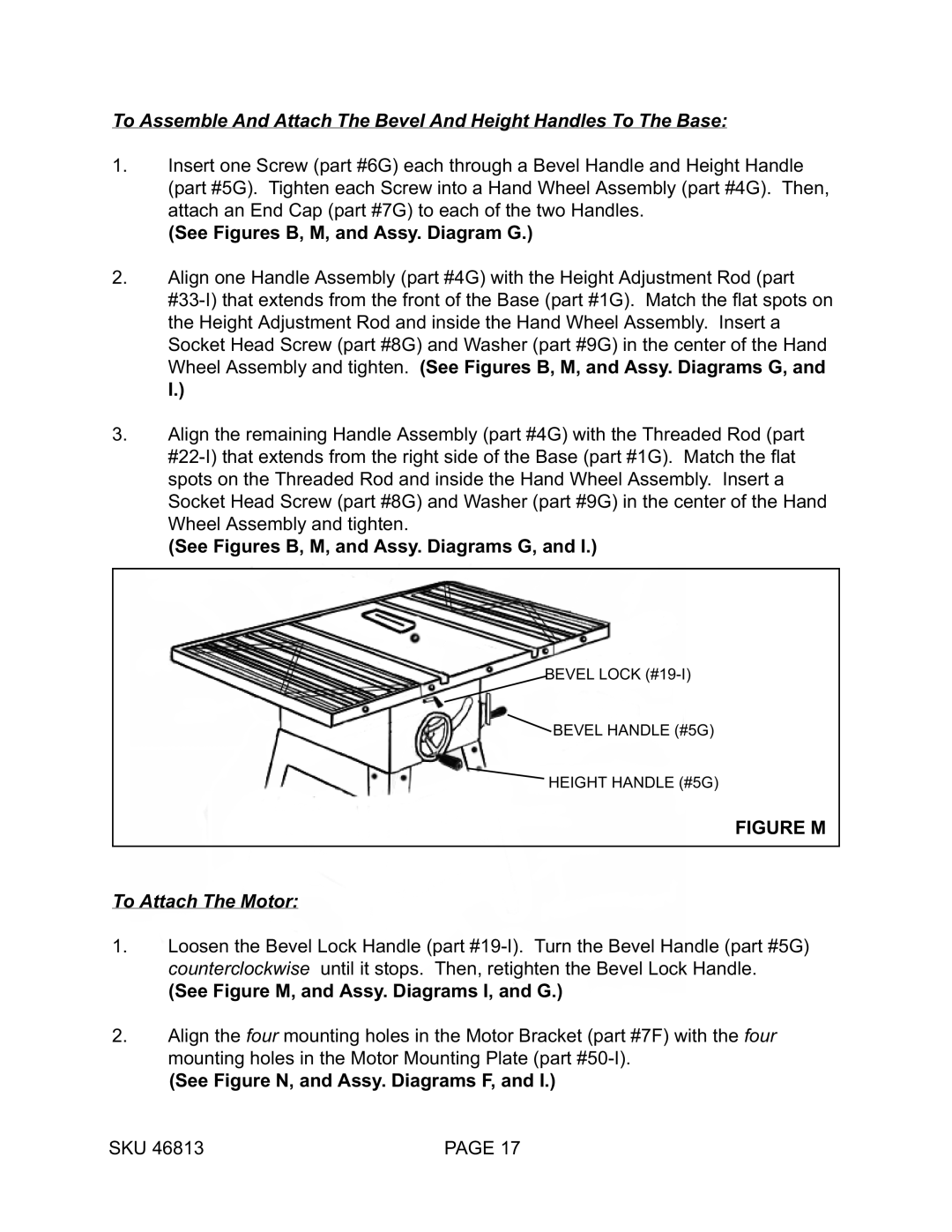
(See Figures B, M, and Assy. Diagrams G, and I.)
BEVEL LOCK
BEVEL HANDLE (#5G)
HEIGHT HANDLE (#5G)
FIGURE M
To Attach The Motor:
1.Loosen the Bevel Lock Handle (part
(See Figure M, and Assy. Diagrams I, and G.)
2.Align the four mounting holes in the Motor Bracket (part #7F) with the four mounting holes in the Motor Mounting Plate (part
(See Figure N, and Assy. Diagrams F, and I.)
SKU 46813 | PAGE 17 |