Contents
For technical questions or replacement parts, please call
220 VAC*DUAL MIG Welder
Contents
Product Specifications
General Safety Rules
Save this Manual
Work Area
Electrical Safety
Personal Safety
Service
Tool USE and Care
Specific Safety Rules
Industrial applications must follow Osha guidelines
Page
Cylinders can explode when damaged
Welding Produces toxic fumes and gasses
Grounding
Symbology
Unpacking
Extension Cords
Grounded Tools Tools with Three Prong Plugs
Assembly Instructions
Face Shield Assembly
To Install a Wire Spool
To Attach The Handle
To Route The Wire
See Figure E
Exercise Extreme Caution Risk of Fire AND/OR Electric Shock
Figure F
Nozzle. See Figure F, previous
To Change Wire Settings
See Figure G
Setting The Gun Polarity For Wire Type
See Figure H
To Install a Gas Cylinder
Operating Instructions
Before You Begin Welding
Duty Cycle Duration of Use
See Figure K
Setting Up The Weld
See Figure L
Holding The Welding Torch
Figure M
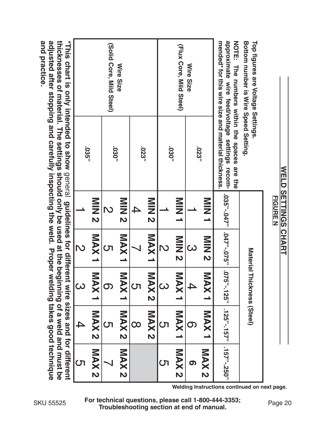
OttomB number is Wire
HarsgCni ttSe eldW
Top figures are Voltage
On ET
Page
Bend at joint
Weld Diagnosis Weld Penetration
Weld Not Adhering Properly
Strike Test
Porosity
Excessive Spatter
When the Weld is Completed
INSPECTION, MAINTENANCE, and Cleaning
Nozzle Inspection, Cleaning, and Replacement
Contact Tip Inspection, Cleaning, And Replacement
Or more for .030Tips .035 or more for .023 Tips
Replacing The Welding Torch Liner
Please Read the Following Carefully
Parts Lists and Diagrams
Wiring Schematic
Parts List
Part Description Qty
Assembly Diagram
Assembly Diagram Wire Feed Mechanism
Troubleshooting
Wire feed motor runs but wire does not feed properly
Wire creates a bird’s nest During operation
Welding arc not stable
Welder does not function when switched on
Wire Feeds, but arc does not ignite
Troubleshooting
Weak Arc strength
Wire Feeds, but Shielding gas does not Flow
Warranty
Nozzle Plugged
Regulator or cylinder valve closed