Assembly Instructions
Note: For additional information regarding the parts listed in the following pages, refer to the Assembly Diagram near the end of this manual.
1.![]() WARNING! Make sure the Power Switch of the tool is in its “OFF” position and that the tool is unplugged from
WARNING! Make sure the Power Switch of the tool is in its “OFF” position and that the tool is unplugged from
its electrical outlet before making any adjustments to the tool.
2.Clean off the protective grease on the Mini Lathe.
To Mount the Lathe to a Workbench:
Drill holes for permanent mounting:
![]()
Figure 5
Unthread the Bolts (67) from the bottom of the unit. Measure and drill holes in the workbench. Use appropriate length
Attaching Rubber Feet or
Installing to Workbench
Note: Mount or place the Lathe on a sturdy workbench or table, with good lighting, at a height that allows you to comfortably work without back strain.
The Lathe can be mounted permanently to a workbench or used with it’s included Rubber Feet (125) on a tabletop.
To Attach the Rubber Feet:
Chip Tray (126) | Bolts (67) |
![]() Rubber Feet (125)
Rubber Feet (125) ![]()
Figure 4 | Bolts (67) |
To attach the Rubber Feet to the bottom of the Lathe, unthread the Bolts (67) from the bottom of the Chip Tray (126). Slide the Rubber Feet onto the Bolts and
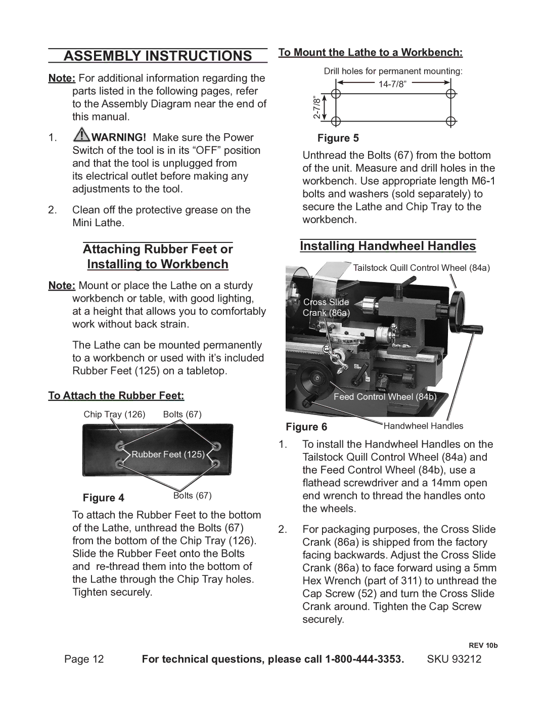
Installing Handwheel Handles
Tailstock Quill Control Wheel (84a)
Cross Slide
Crank (86a)
Feed Control Wheel (84b)
Figure 6 | Handwheel Handles |
1.To install the Handwheel Handles on the Tailstock Quill Control Wheel (84a) and the Feed Control Wheel (84b), use a flathead screwdriver and a 14mm open end wrench to thread the handles onto the wheels.
2.For packaging purposes, the Cross Slide Crank (86a) is shipped from the factory facing backwards. Adjust the Cross Slide Crank (86a) to face forward using a 5mm Hex Wrench (part of 311) to unthread the Cap Screw (52) and turn the Cross Slide Crank around. Tighten the Cap Screw securely.
REV 10b
Page 12 | For technical questions, please call | SKU 93212 |