AVR 3550HD
Important Safety Instructions
Safety Information
Do not place the unit directly on a carpeted surface
Important Safety Information
Table of Contents
Harman Kardon AVR 3550HD 7.1-Channel Audio/Video Receiver
Introduction
Thank you for choosing a Harman Kardon product
Audio Section
Audio Inputs
Supplied Accessories
Audio/Video Inputs
Digital Audio Inputs
FRONT-PANEL Controls
Volume Knob Turn this knob to raise or lower the volume
Power Indicator This LED has three possible modes
On When the AVR is turned on, this LED turns white
REAR-PANEL Connections
REAR-PANEL Connections
REAR-PANEL Connections
Main Remote Control Functions
Main Remote Control Functions
Main Remote Control Functions
Zone 2 Remote Control Functions
Zone 2 Remote Control Functions
Surround Modes
Introduction to Home Theater
Typical Home Theater System
Multichannel Audio
Connections
Connecting Source Devices to the AVR
Speaker Connections
Subwoofer
Digital Video
Video Connections
Analog Video
Hdmi cable runs are limited to about 10 feet
RS-232 Serial Port
FM antenna uses a 75-ohm F-connector. See Figure
Antennas
Front Speaker Placement
Speaker Placement
Placement of Surround Speakers in a 5.1-Channel System
Placement of Surround Speakers in a 7.1-Channel System
Step One Connect the Speakers
Installation
Step Two Connect the Subwoofer
Step Three Connect the Antennas
Video Connections for non-HDMI sources
Audio Connections for non-HDMI sources
Choose one digital audio connection Optical or Coaxial
Hdmi Video Connect the player as shown in Figure
Hdmi Video Connect the recorder as shown in Figure
Connect an Audio/Video Recorder PVD, DVR or TiVo
Connecting a Game Console, Camera or Other Device
Connect an iPod Using Docking Station
Connect a CD Player or Any Audio-Only Device
Connect a Tape Deck or Any Audio-Only Recorder
Step Five Connect the Video Display
Step Six Plug in AC Power
Satisfactory code set that operates most functions
Step Seven Insert Batteries in Remote
Enter a code from , above
Learning
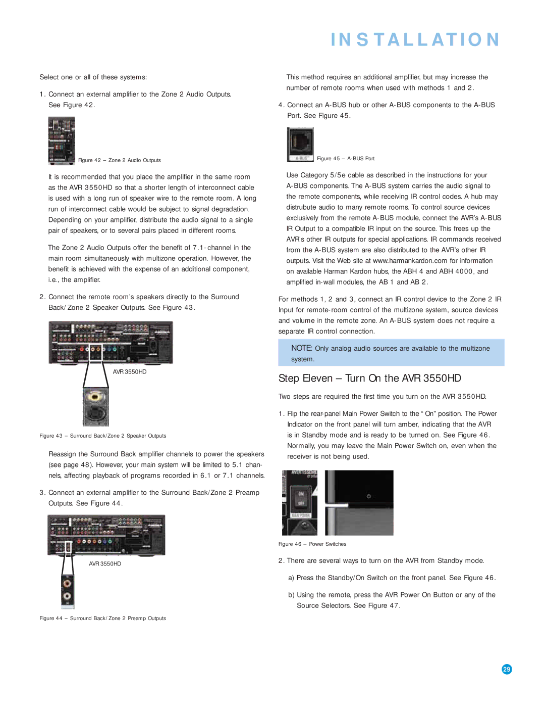
Step Ten Install a Multizone System Optional
Zone 2 Audio Outputs
Step Eleven Turn On the AVR 3550HD
AVR Power On and Source Selectors
Configure the AVR 3550HD Using EzSet/EQ Technology
Initial Setup
Using the On-Screen Menu System
Select Cancel to return to the Speaker Setup menu
Set Up Sources
HDMI-Equipped Multichannel Disc Player
Audio and Video Input Selection
Channel Direct Inputs
You are now ready to begin enjoying your new receiver
‹ / › Buttons to delay the audio by up to 180ms. See Figure
Operation
XM Radio Operation
Using the Tuner
Source Selection
To store a channel in one of the 40 preset locations
Using Docking Station
Press the OK Button to store the new preset
Recording
Music Navigates the audio materials stored on the iPod
Selecting a Surround Mode
Press the Menu Button to view the slide-out menu
Auto SELECT, Surr VIRTUAL, Surr STEREO, Surr MOVIE, Surr
CH Stereo plays the left-channel signal through the front
Digital Audio Signals
Analog Audio Signals
Advanced Functions
Audio Processing and Surround Sound
Indicates that no surround information is present
Dolby Surround Settings
Step Three Manual Setup Menu
Manual Setup
Night Mode
Step Two Measure Speaker Distances
Number of Speakers
Adjust Crossover Frequencies Menu
Sub Mode
Adjust Speaker Distance Menu
Step Four Setting Channel Output Levels Manually
Tone Control Determines whether the treble and bass
Video Adjustments
Brightness Adjustment
How to Adjust the Custom Picture Settings
Nature For programs shot outdoors, in a natural setting
Sports For sporting events
Multizone Operation
General AVR Settings
System Settings
Operating the Multizone System
Menu Appearance
Resetting the Remote
Advanced Remote Control Functions
Punch-Through Programming
Activities Macros
Memory
Processor Reset
Troubleshooting Guide
Table A2 Source Setting Defaults
Appendix Default settings, worksheets, remote product codes
Appendix
Table A1 Recommended Source Component Connections
Table A4 Delay Setting Defaults
Table A3 Speaker/Channel Setting Defaults
Table A7 Video Modes Settings
Table A5 Source Settings
Table A6 Audio Effects Settings
Table A8 Surround Modes
Table A9 Remote Control Codes
Table A10 System Settings
Table A12 Surround Modes
Table A11 Zone 2 Settings
Experience Tuner
Mode Group Enveloping sound field is desired
Movie Back channel 0 or .1, EX Analog 2-channel Tuner
Music adds a surround back channel Analog 2-channel Tuner
Rate used on DVD-Video discs
Surround Mode Description Incoming Bitstream or Signal
Performance Via Hdmi DTS-ES Matrix
DTS Stereo
Channel Stereo
Appropriate when a subwoofer is used
Channels Tuner PCM 32kHz, 44.1kHz or 48kHz Channel Stereo
Analog Bypass
41 42
DMC1000
Table A13 Remote Control Function List
Radio
Table A13
Power Off
Button Name
Game
Aiwa
Table A15 Remote Control Product Codes AUX-HDTV
Table A16 Remote Control Product Codes AUX-VCR
Table A14
Table A16
Table A17
Table A18 Remote Control Product Codes DVD
Table A21 Remote Control Product Codes CBL
Table A19 Remote Control Product Codes SAT
Table A20 Remote Control Product Codes Game
Table A23 Remote Control Product Codes
Table A22 Remote Control Product Codes
Table A24 Remote Control Product Codes AUX- TiVo
Table A21
Channels driven Dimensions Product Shipping Width
General Power Requirement AC 120V/60Hz Power Consumption
Product Shipping Weight 31.5 lb 14.3kg 36.7 lb 16.7kg
Linear High-Level 200mV/47k ohms