CABLE ASSEMBLY
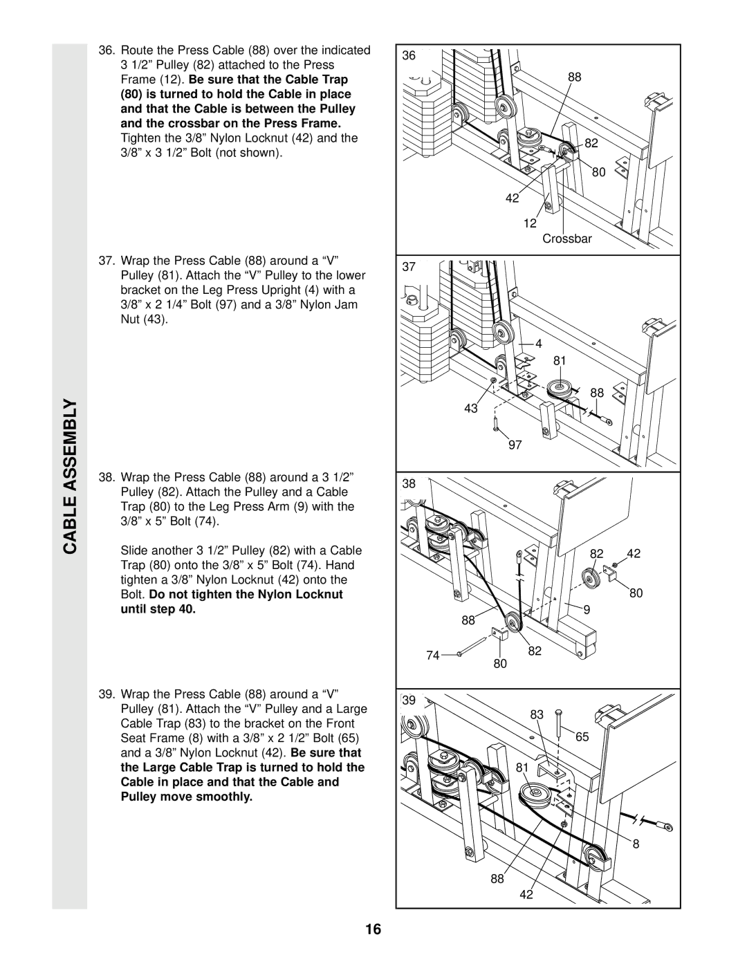
36. Route the Press Cable (88) over the indicated |
| 36 |
|
| |
3 1/2” Pulley (82) attached to the Press |
|
|
| ||
|
| 88 |
| ||
Frame (12). | Be sure that the Cable Trap |
|
| ||
(80) is turned to hold the Cable in place |
|
|
| ||
and that the Cable is between the Pulley |
|
|
| ||
and the crossbar on the Press Frame. |
|
|
|
| |
Tighten the 3/8” Nylon Locknut (42) and the |
| 82 |
| ||
3/8” x 3 1/2” Bolt (not shown). |
|
|
| ||
|
|
|
| ||
|
|
|
| 80 |
|
|
|
|
| 42 |
|
|
|
|
| 12 |
|
|
|
|
| Crossbar |
|
37. Wrap the Press Cable (88) around a “V” |
| 37 |
|
| |
Pulley (81). Attach the “V” Pulley to the lower |
|
| |||
|
|
| |||
bracket on the Leg Press Upright (4) with a |
|
|
|
| |
3/8” x 2 1/4” Bolt (97) and a 3/8” Nylon Jam |
|
|
| ||
Nut (43). |
|
|
|
|
|
|
|
|
| 4 |
|
|
|
|
| 81 |
|
|
|
|
| 88 |
|
|
|
|
| 43 |
|
|
|
|
| 97 |
|
38. Wrap the Press Cable (88) around a 3 1/2” |
| 38 |
|
| |
Pulley (82). Attach the Pulley and a Cable |
|
|
| ||
|
|
|
| ||
Trap (80) to the Leg Press Arm (9) with the |
|
|
|
| |
3/8” x 5” Bolt (74). |
|
|
|
| |
Slide another 3 1/2” Pulley (82) with a Cable |
| 82 | 42 | ||
Trap (80) onto the 3/8” x 5” Bolt (74). Hand |
|
|
| ||
tighten a 3/8” Nylon Locknut (42) onto the |
|
| 80 | ||
Bolt. Do not tighten the Nylon Locknut |
|
|
| ||
until step 40. |
|
|
| 9 |
|
|
|
|
| 88 |
|
|
|
| 74 | 82 |
|
|
|
| 80 |
| |
|
|
|
|
| |
39. Wrap the Press Cable (88) around a “V” |
| 39 |
|
| |
Pulley (81). Attach the “V” Pulley and a Large |
|
| |||
| 83 |
| |||
Cable Trap (83) to the bracket on the Front |
|
|
| ||
|
| 65 |
| ||
Seat Frame (8) with a 3/8” x 2 1/2” Bolt (65) |
|
| |||
and a 3/8” Nylon Locknut (42). | Be sure that |
|
|
| |
the Large Cable Trap is turned to hold the |
| 81 |
| ||
Cable in place and that the Cable and |
|
|
|
| |
Pulley move smoothly. |
|
|
|
| |
|
|
|
|
| 8 |
|
|
|
| 88 |
|
|
|
|
| 42 |
|
16
