F. Vent Diagrams
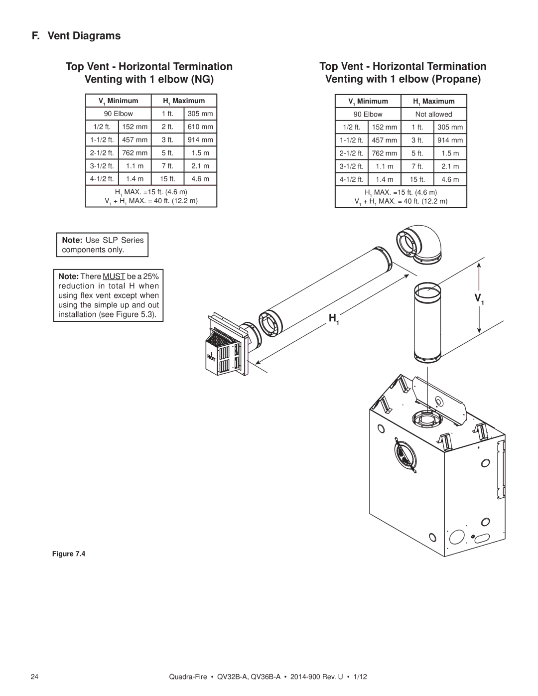
Top Vent - Horizontal Termination
Venting with 1 elbow (NG)
V1 Minimum | H1 Maximum | ||
90 Elbow | 1 ft. | 305 mm | |
1/2 ft. | 152 mm | 2 ft. | 610 mm |
|
|
|
|
457 mm | 3 ft. | 914 mm | |
|
|
|
|
762 mm | 5 ft. | 1.5 m | |
|
|
|
|
1.1 m | 7 ft. | 2.1 m | |
|
|
|
|
1.4 m | 15 ft. | 4.6 m | |
|
|
|
|
H1 MAX. =15 ft. (4.6 m)
V1 + H1 MAX. = 40 ft. (12.2 m)
Note: Use SLP Series components only.
Note: There MUST be a 25% reduction in total H when using flex vent except when using the simple up and out installation (see Figure 5.3).
Figure 7.4
Top Vent - Horizontal Termination
Venting with 1 elbow (Propane)
V1 Minimum | H1 Maximum | ||
90 Elbow | Not allowed | ||
|
|
|
|
1/2 ft. | 152 mm | 1 ft. | 305 mm |
|
|
|
|
457 mm | 3 ft. | 914 mm | |
|
|
|
|
762 mm | 5 ft. | 1.5 m | |
1.1 m | 7 ft. | 2.1 m | |
|
|
|
|
1.4 m | 15 ft. | 4.6 m | |
|
|
|
|
H1 MAX. =15 ft. (4.6 m)
V1 + H1 MAX. = 40 ft. (12.2 m)
V1
H1
24 |