12 Electrical Information
A. Wiring Requirements
NOTICE: This appliance must be electrically wired and grounded in accordance with local codes or, in the absence of local codes, with National Electric Code ANSI/NFPA
Code CSA C22.1.
•Wire the appliance junction box to
•A
•Low voltage and 110 VAC voltage cannot be shared within the same wall box.
WARNING! Risk of Shock or Explosion! DO NOT wire 110V to the valve or to the appliance wall switch. Incorrect wiring will damage controls.
C. Optional Accessories Requirements
•This appliance may be used with a wall switch, wall mounted thermostat and/or a remote control.
Wiring for optional Hearth & Home Technologies approved accessories should be done now to avoid reconstruction. Follow instructions that come with those accessories.
D. Electrical Service and Repair
WARNING! Risk of Shock! Label all wires prior to dis- connection when servicing controls. Wiring errors can cause improper and dangerous operation. Verify proper operation after servicing.
WARNING! Risk of Shock! Replace damaged wire with type 105º C rated wire. Wire must have high temperature insulation.
B. Standing Pilot Ignition System Wiring
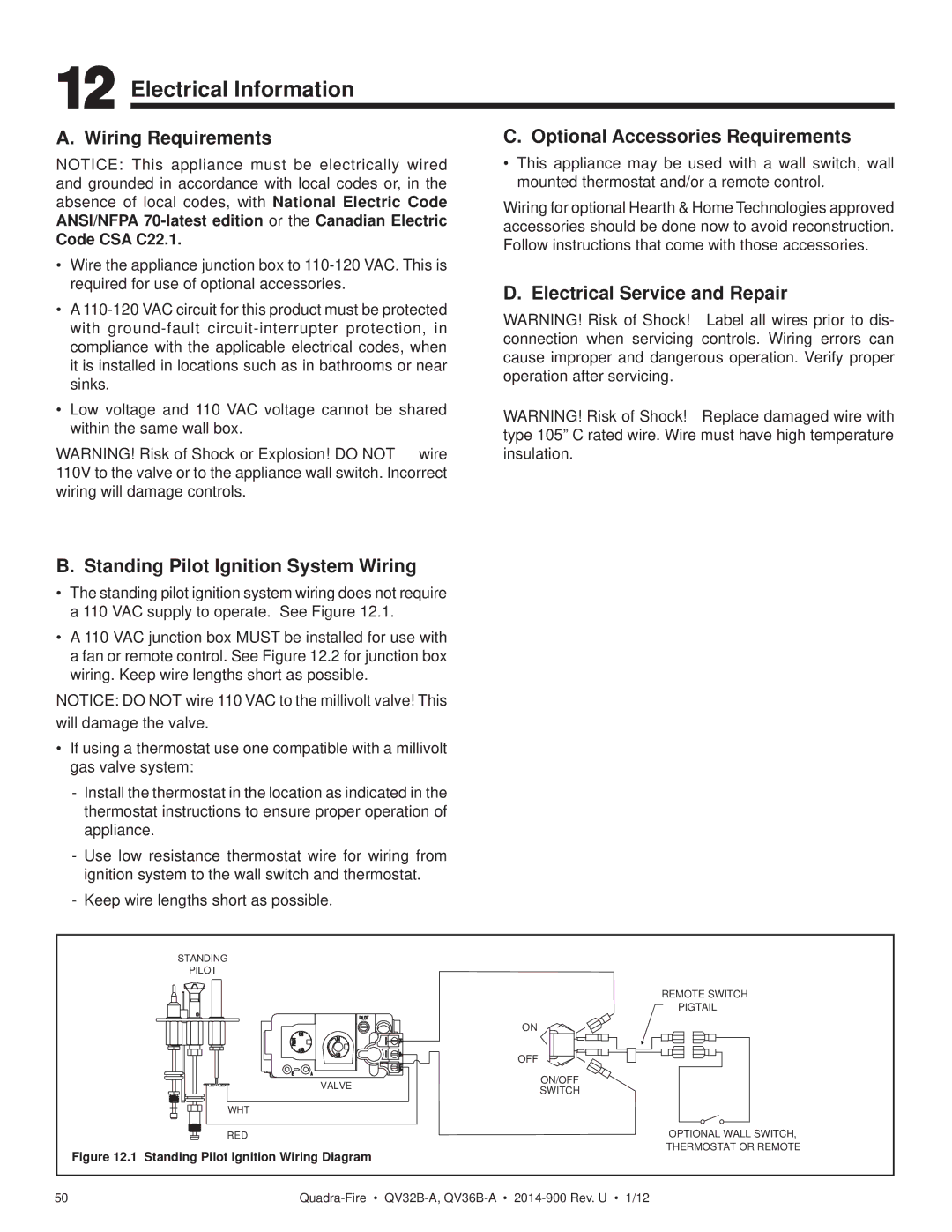
•The standing pilot ignition system wiring does not require a 110 VAC supply to operate. See Figure 12.1.
•A 110 VAC junction box MUST be installed for use with a fan or remote control. See Figure 12.2 for junction box wiring. Keep wire lengths short as possible.
NOTICE: DO NOT wire 110 VAC to the millivolt valve! This will damage the valve.
•If using a thermostat use one compatible with a millivolt gas valve system:
-Install the thermostat in the location as indicated in the thermostat instructions to ensure proper operation of appliance.
-Use low resistance thermostat wire for wiring from ignition system to the wall switch and thermostat.
-Keep wire lengths short as possible.
STANDING
PILOT
REMOTE SWITCH
PIGTAIL
| ON | |
| OFF | |
VALVE | ON/OFF | |
SWITCH | ||
| ||
WHT |
| |
RED |
|
Figure 12.1 Standing Pilot Ignition Wiring Diagram
OPTIONAL WALL SWITCH, THERMOSTAT OR REMOTE
50 |