NOT
USED
T O
GROUND
CLIP
WALL
SWITCH
BACK VIEW
CORD
ASSEMBLY
2
ORG
WHT
BLK
BATTERY
PACK
CONNECT TO ORIFICE SOLENOID
RED WIRE TO RED WIRE
BLACK WIRE TO BLACK WIRE
NOT
CONNECTED
F.O.L. CAPACITOR
PART IS ENCLOSED
IN SHRINK TUBING
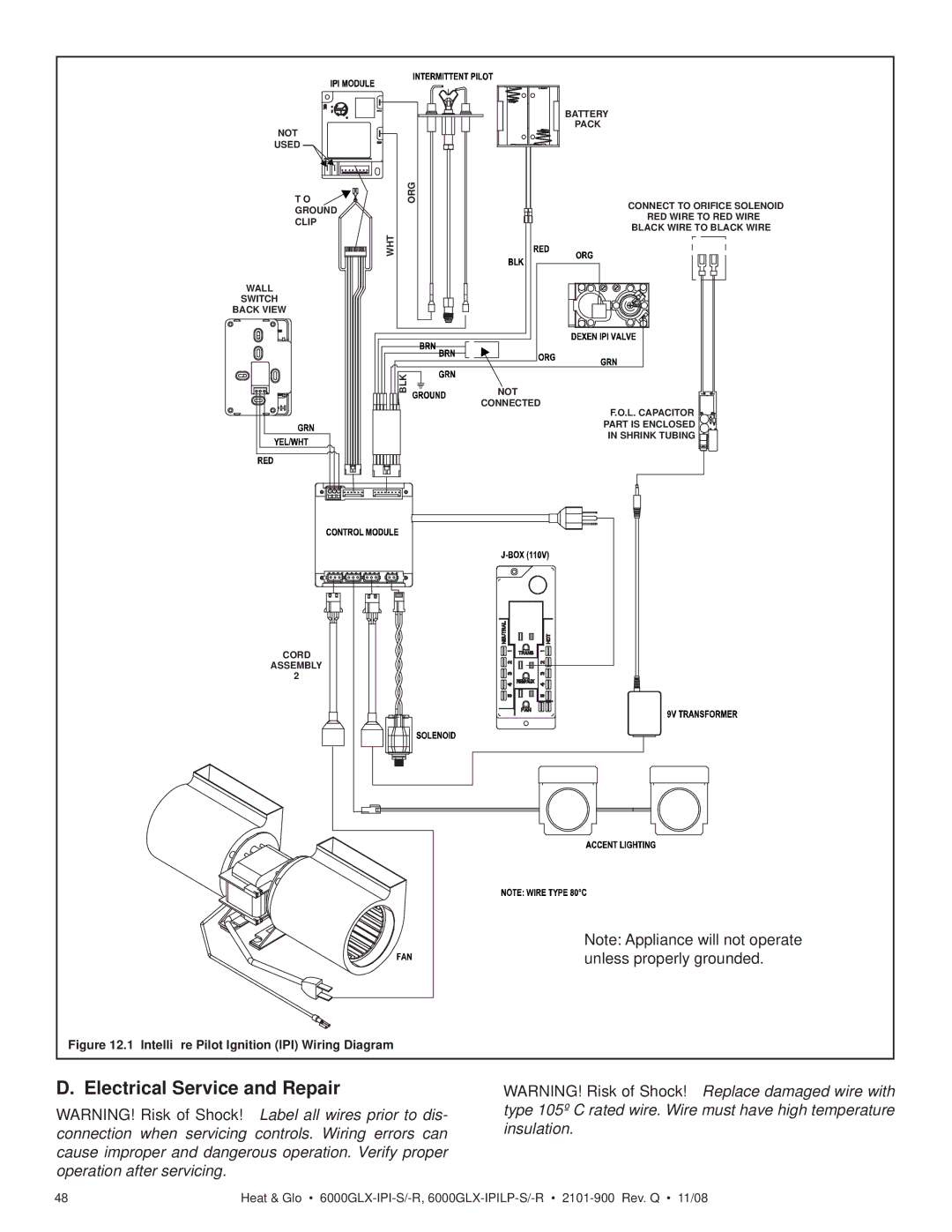
Note: Appliance will not operate unless properly grounded.
Figure 12.1 Intellifire Pilot Ignition (IPI) Wiring Diagram
D. Electrical Service and Repair
WARNING! Risk of Shock! Label all wires prior to dis- connection when servicing controls. Wiring errors can cause improper and dangerous operation. Verify proper operation after servicing.
WARNING! Risk of Shock! Replace damaged wire with type 105º C rated wire. Wire must have high temperature insulation.
48 | Heat & Glo • |