16 Reference Materials
A. Appliance Dimension Diagram
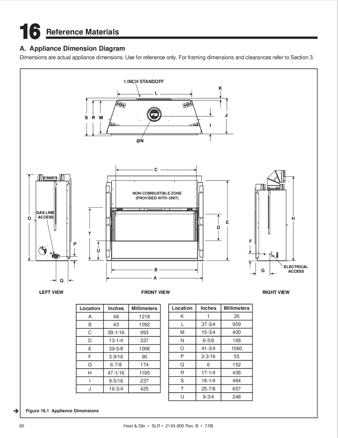
Dimensions are actual appliance dimensions. Use for reference only. For framing dimensions and clearances refer to Section 3.
GAS LINE
OACCESS
Q
LEFT VIEW
1 INCH STANDOFF
K
L
S R M 
![]() J I
J I
ØN
C
(PROVIDED WITH UNIT)
E D
T
P ![]()
![]() F U
F U![]()
B
A
FRONT VIEW
H
![]() ELECTRICAL
ELECTRICAL
G ACCESS
RIGHT VIEW
Location | Inches | Millimeters |
A | 48 | 1218 |
B | 43 | 1092 |
C | 993 | |
D | 337 | |
E | 1006 | |
F | 90 | |
G | 174 | |
H | 1195 | |
I | 237 | |
J | 425 |
Location | Inches | Millimeters |
K | 1 | 25 |
L | 959 | |
M | 400 | |
N | 168 | |
O | 1060 | |
P | 55 | |
Q | 6 | 152 |
R | 438 | |
S | 464 | |
T | 657 | |
U | 248 |
Î
Figure 16.1 Appliance Dimensions
60 | Heat & Glo • SLR • |
