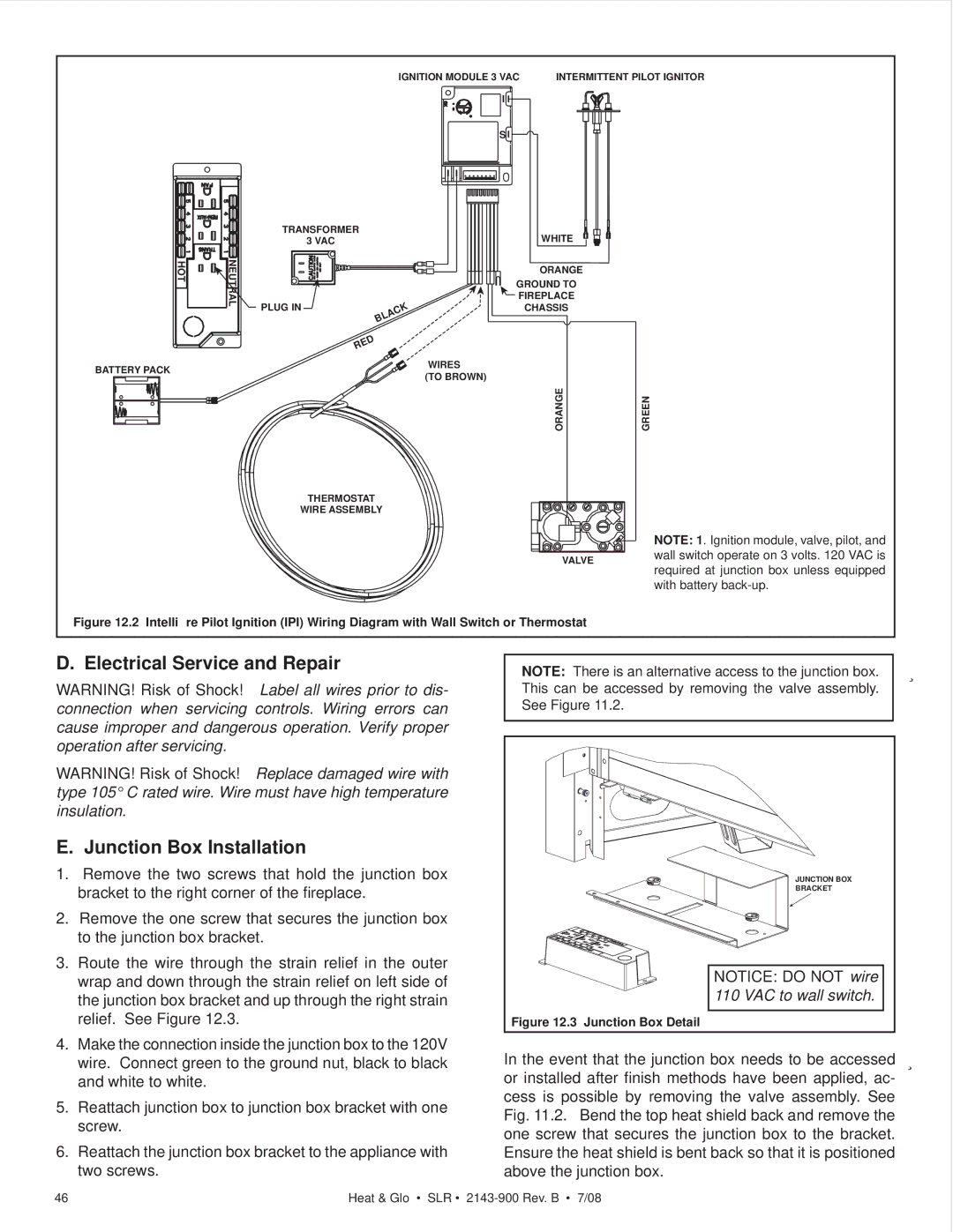
IGNITION MODULE 3 VAC | INTERMITTENT PILOT IGNITOR |
I
S
TRANSFORMER | WHITE |
3 VAC |
HOT | NEUTRAL |
BATTERY PACK
PLUG IN
BLACK
RED
ORANGE
GROUND TO
![]() FIREPLACE
FIREPLACE
CHASSIS
WIRES
(TO BROWN)
ORANGE | GREEN |
THERMOSTAT
WIRE ASSEMBLY
VALVE
NOTE: 1. Ignition module, valve, pilot, and wall switch operate on 3 volts. 120 VAC is required at junction box unless equipped with battery
Figure 12.2 Intellifire Pilot Ignition (IPI) Wiring Diagram with Wall Switch or Thermostat
D. Electrical Service and Repair
WARNING! Risk of Shock! Label all wires prior to dis- connection when servicing controls. Wiring errors can cause improper and dangerous operation. Verify proper operation after servicing.
WARNING! Risk of Shock! Replace damaged wire with type 105° C rated wire. Wire must have high temperature insulation.
E. Junction Box Installation
1.Remove the two screws that hold the junction box bracket to the right corner of the fireplace.
2.Remove the one screw that secures the junction box to the junction box bracket.
3.Route the wire through the strain relief in the outer wrap and down through the strain relief on left side of the junction box bracket and up through the right strain relief. See Figure 12.3.
4.Make the connection inside the junction box to the 120V wire. Connect green to the ground nut, black to black and white to white.
5.Reattach junction box to junction box bracket with one screw.
6.Reattach the junction box bracket to the appliance with two screws.
NOTE: There is an alternative access to the junction box. | Î |
This can be accessed by removing the valve assembly. |
|
See Figure 11.2. |
|
|
|
JUNCTION BOX
BRACKET
NOTICE: DO NOT wire |
|
110 VAC to wall switch. |
|
Figure 12.3 Junction Box Detail |
|
In the event that the junction box needs to be accessed | Î |
or installed after finish methods have been applied, ac- |
|
cess is possible by removing the valve assembly. See |
|
Fig. 11.2. Bend the top heat shield back and remove the |
|
one screw that secures the junction box to the bracket. |
|
Ensure the heat shield is bent back so that it is positioned |
|
above the junction box. |
|
46 | Heat & Glo • SLR • |