INSTALLATION INSTRUCTIONS (continued)
Connecting to an Audio Visual Device
(1)Make sure that the power switch of the monitor is turned off.
(2)Make sure that the power switch of the imaging device is turned off.
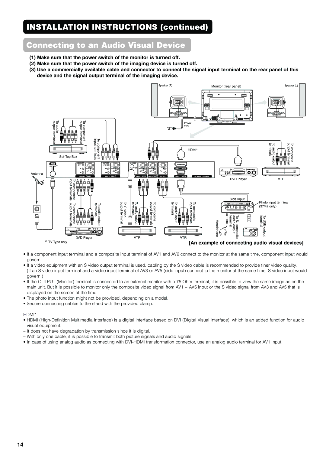
(3)Use a commercially available cable and connector to connect the signal input terminal on the rear panel of this device and the signal output terminal of the imaging device.
Speaker (R) |
|
|
|
|
|
|
| Monitor (rear panel) |
| Speaker (L) | ||
|
|
|
|
|
|
|
|
|
|
|
|
|
|
|
|
|
|
|
|
|
|
|
|
|
|
|
|
|
|
|
|
|
|
|
|
|
|
|
|
|
|
|
|
|
|
|
|
|
|
|
|
|
|
|
|
|
|
|
|
|
|
|
|
|
|
|
|
|
|
|
|
|
|
|
|
|
|
|
|
|
|
|
|
|
|
|
|
|
|
|
|
|
|
|
|
|
|
|
|
|
|
|
|
To audio output terminals | To component output terminals | Tocomponent inputterminals |
|
|
Power cord
To audio output terminals | To composite output terminal |
Antenna
input terminals | To component |
|
|
output terminals | To component | To audio output terminals | To S video output terminal |
To audio output terminals | To composite output terminals |
|
|
| DVD Player | VTR |
|
|
| Side Input | Photo input terminal |
To audio input terminals | To composite input terminals |
|
| |
|
| (37/42 only) | ||
Headphone | To S,composite audio output terminal | To USB output terminal |
DVD Player | VTR |
![]() TV Type only
TV Type only
VTR
[An example of connecting audio visual devices]
•If a component input terminal and a composite input terminal of AV1 and AV2 connect to the monitor at the same time, component input would govern.
•If a video equipment with an S video output terminal is used, cabling by the S video cable is recommended to provide finer video quality.
(If an S video input terminal and a video input terminal of AV3 or AV5 (side input) connect to the monitor at the same time, S video input would govern.)
•If the OUTPUT (Monitor) terminal is connected to an external monitor with a 75 Ohm terminal, it is possible to view the same image as on the main unit. But it is possible to monitor only the composite video signal from AV1 ~ AV5 input or the S video signal from AV3 and AV5 that is displayed on the screen at the time.
•The photo input function might not be provided, depending on a model.
•Secure connecting cables to the stand with the provided clamp.
HDMI*
•HDMI
–It does not have degradation by transmission since it is digital.
–With only one cable, it is possible to transmit both picture signals and audio signals.
• In case of using analog audio as connecting with
14
