Index to Parts and Controls
Refer to the pages indicated in parentheses for details.
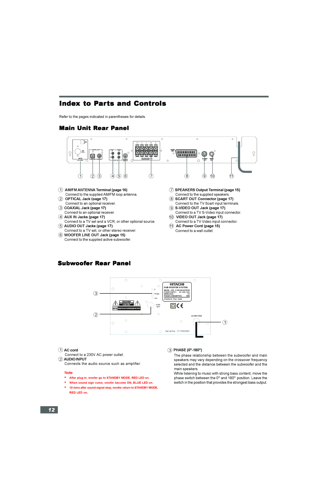
Main Unit Rear Panel
AM |
FR FL C SR SL
AUDIO AUDIO
IN OUT
L |
R |
(8 | ) |
AUX IN |
|
1 | 2 | 3 | 4 | 5 | 6 | 7 |
1AM/FM ANTENNA Terminal (page 16) Connect to the supplied AM/FM loop antenna.
2OPTICAL Jack (page 17) Connect to an optional receiver.
3COAXIAL Jack (page 17) Connect to an optional receiver.
4AUX IN Jacks (page 17)
Connect to a TV set and a VCR, or other optional source.
5AUDIO OUT Jacks (page 17)
Connect to a TV set, or other stereo receiver.
6WOOFER LINE OUT Jack (page 15) Connect to the supplied active subwoofer.
8 | 9 | 10 | 11 |
7SPEAKERS Output Terminal (page 15) Connect to the supplied speakers.
8SCART OUT Connector (page 17) Connect to the TV Scart input terminals.
9
Connect to a TV
10VIDEO OUT Jack (page 17) Connect to a TV Video input connector.
11AC Power Cord (page 15)
Connect to a wall outlet.
Subwoofer Rear Panel
3
2
1
1AC cord
Connect to a 230V AC power outlet.
2AUDIO INPUT
Connects the audio source such as amplifier.
Note
•After plug in, woofer go to STANDBY MODE, RED LED on.
•When sound sign come, woofer become ON, BLUE LED on.
•10 mins after sound signal stop, woofer return to STANDBY MODE, RED LED on.
3PHASE (0O-180O)
The phase relationship between the subwoofer and main speakers may vary depending on the crossover frequency selected and the distance between the subwoofer and the main speakers.
While listening to music with strong bass content, move the phase switch between the 0O and 180O position. Leave the switch in the position that provides the strongest bass output.
12