|
|
|
|
| Chapter 4 | WIRING AND CONNECTION |
| |||||
|
|
|
|
|
|
|
|
|
|
|
| |
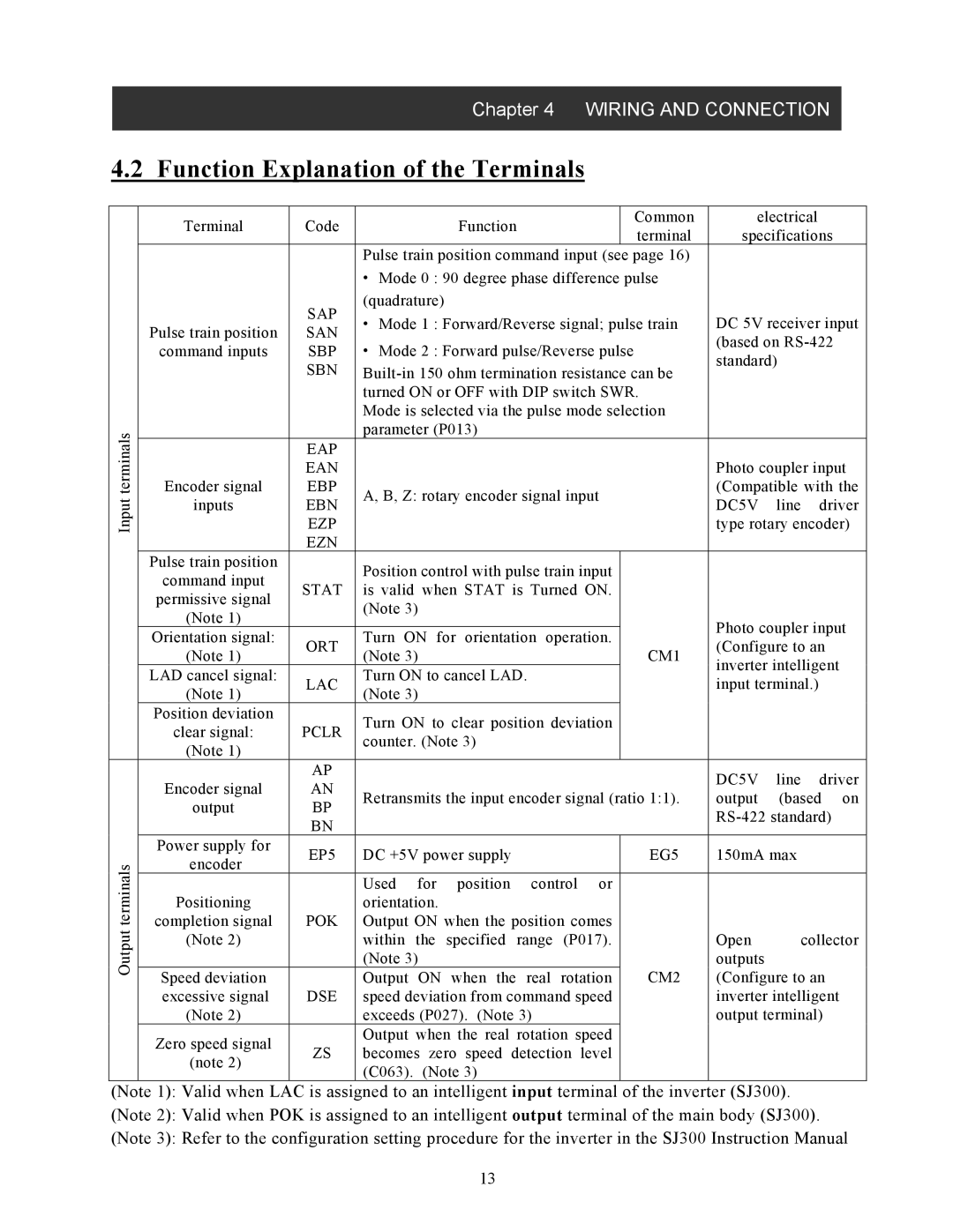
4.2 | Function Explanation of the Terminals |
|
|
|
|
| ||||||
|
|
|
|
|
|
|
|
|
|
|
| |
|
|
| Terminal | Code | Function |
|
| Common | electrical |
|
| |
|
|
|
|
| terminal | specifications | ||||||
|
|
|
|
|
|
|
| |||||
|
|
|
|
| Pulse train position command input (see page 16) |
|
|
|
| |||
|
|
|
|
| • Mode 0 : 90 degree phase difference pulse |
|
|
|
| |||
|
|
|
| SAP | (quadrature) |
|
|
|
|
|
|
|
|
|
|
| • Mode 1 : Forward/Reverse signal; pulse train | DC 5V receiver input | |||||||
|
|
| Pulse train position | SAN | ||||||||
|
|
| • Mode 2 : Forward pulse/Reverse pulse |
| (based on | |||||||
|
|
| command inputs | SBP |
| |||||||
|
|
|
| standard) |
|
| ||||||
|
|
|
| SBN |
|
| ||||||
|
|
|
|
|
|
|
| |||||
|
|
|
|
| turned ON or OFF with DIP switch SWR. |
|
|
|
| |||
|
|
|
|
| Mode is selected via the pulse mode selection |
|
|
|
| |||
| terminals |
|
|
| parameter (P013) |
|
|
|
|
|
|
|
|
| Encoder signal | EBP |
|
|
|
| (Compatible with the | ||||
|
|
|
| EAP |
|
|
|
|
|
|
|
|
|
|
|
| EAN |
|
|
|
| Photo coupler input | |||
| Input |
| inputs | EBN | A, B, Z: rotary encoder signal input |
| DC5V | line | driver | |||
|
|
|
|
|
| |||||||
|
|
| EZP |
|
|
|
| type rotary encoder) | ||||
|
|
|
| EZN |
|
|
|
|
|
|
|
|
|
|
| Pulse train position |
| Position control with pulse train input |
|
|
|
|
|
| |
|
|
| command input |
|
|
|
|
|
|
| ||
|
|
| STAT | is valid when STAT is Turned ON. |
|
|
|
|
|
| ||
|
|
| permissive signal |
|
|
|
|
|
| |||
|
|
|
| (Note 3) |
|
|
|
|
|
|
| |
|
|
| (Note 1) |
|
|
|
| Photo coupler input | ||||
|
|
|
|
|
|
|
| |||||
|
|
| Orientation signal: | ORT | Turn ON for orientation operation. |
|
| |||||
|
|
|
|
| (Configure to an | |||||||
|
|
| (Note 1) | (Note 3) |
|
| CM1 | |||||
|
|
|
|
|
| inverter intelligent | ||||||
|
|
| LAD cancel signal: |
| Turn ON to cancel LAD. |
|
|
| ||||
|
|
| LAC |
|
|
| input terminal.) |
|
| |||
|
|
| (Note 1) | (Note 3) |
|
|
|
|
| |||
|
|
|
|
|
|
|
|
|
|
| ||
|
|
| Position deviation |
| Turn ON to clear position deviation |
|
|
|
|
|
| |
|
|
| clear signal: | PCLR |
|
|
|
|
|
| ||
|
|
| counter. (Note 3) |
|
|
|
|
|
|
| ||
|
|
| (Note 1) |
|
|
|
|
|
|
|
| |
|
|
|
|
|
|
|
|
|
|
|
| |
|
|
|
| AP |
|
|
|
| DC5V | line | driver | |
|
|
| Encoder signal | AN |
|
|
|
| ||||
|
|
| Retransmits the input encoder signal (ratio 1:1). | output | (based on | |||||||
|
|
| output | BP | ||||||||
|
|
|
|
|
|
| ||||||
|
|
|
| BN |
|
|
|
| ||||
|
|
|
|
|
|
|
|
|
|
|
| |
|
|
| Power supply for | EP5 | DC +5V power supply |
|
| EG5 | 150mA max |
|
| |
| terminals |
| encoder |
|
|
|
| |||||
|
|
|
|
|
|
|
|
|
|
| ||
|
| completion signal | POK | Output ON when the position comes |
|
|
|
|
|
| ||
|
|
|
|
| Used for position control or |
|
|
|
|
|
| |
| Output |
| Positioning |
| orientation. |
|
|
|
|
|
|
|
|
| (Note 2) |
| within the specified range (P017). |
|
| Open | collector | ||||
|
|
|
|
|
| |||||||
|
|
|
|
| (Note 3) |
|
|
| outputs |
|
|
|
|
|
| Speed deviation |
| Output ON when the real rotation |
| CM2 | (Configure to an | ||||
|
|
| excessive signal | DSE | speed deviation from command speed |
|
| inverter intelligent | ||||
|
|
| (Note 2) |
| exceeds (P027). (Note 3) |
|
|
| output terminal) | |||
|
|
| Zero speed signal |
| Output when the real rotation speed |
|
|
|
|
|
| |
|
|
| ZS | becomes zero speed detection | level |
|
|
|
|
|
| |
|
|
| (note 2) |
|
|
|
|
|
| |||
|
|
|
| (C063). (Note 3) |
|
|
|
|
|
|
| |
|
|
|
|
|
|
|
|
|
|
|
| |
(Note 1): Valid when LAC is assigned to an intelligent input terminal of the inverter (SJ300).
(Note 2): Valid when POK is assigned to an intelligent output terminal of the main body (SJ300).
(Note 3): Refer to the configuration setting procedure for the inverter in the SJ300 Instruction Manual
13