Chapter 4 WIRING AND CONNECTION
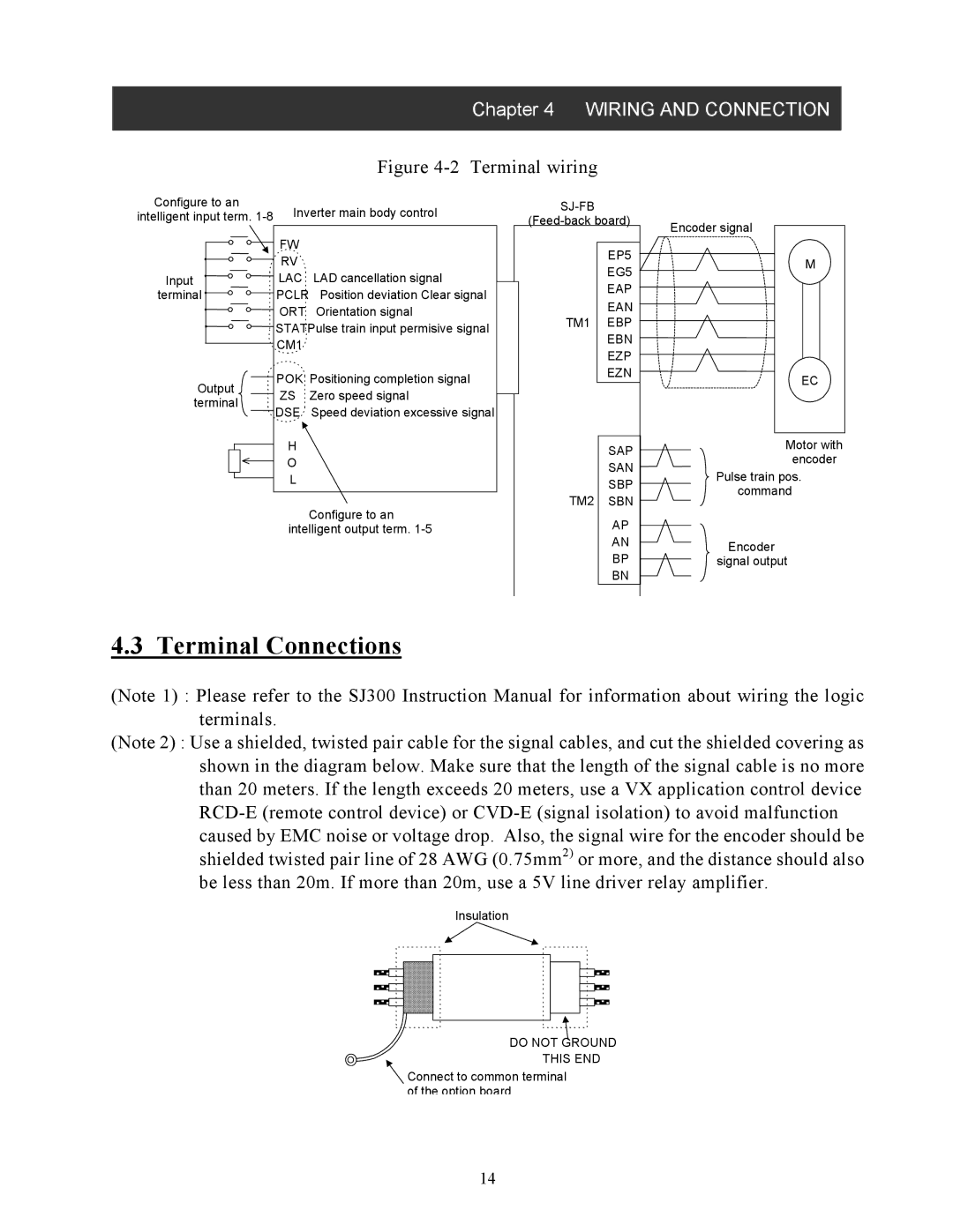
Figure 4-2 Terminal wiring
Configure to an | Inverter main body control | ||
intelligent input term. | |||
| FW |
| |
| RV |
| |
Input | LAC | LAD cancellation signal | |
terminal | PCLR | Position deviation Clear signal | |
| ORT | Orientation signal | |
| STATPulse train input permisive signal | ||
| CM1 |
| |
Output | POK | Positioning completion signal | |
ZS | Zero speed signal | ||
terminal | |||
DSE | Speed deviation excessive signal | ||
| |||
H
O
L
Configure to an intelligent output term.
EP5
EG5
EAP
EAN
TM1 EBP
EBN
EZP
EZN
SAP
SAN
SBP
TM2 SBN
AP
AN
BP
BN
Encoder signal
M |
EC |
Motor with encoder
Pulse train pos. command
Encoder signal output
4.3 Terminal Connections
(Note 1) : Please refer to the SJ300 Instruction Manual for information about wiring the logic terminals.
(Note 2) : Use a shielded, twisted pair cable for the signal cables, and cut the shielded covering as shown in the diagram below. Make sure that the length of the signal cable is no more than 20 meters. If the length exceeds 20 meters, use a VX application control device
Insulation
DO NOT GROUND THIS END
Connect to common terminal of the option board.
14