[Setting example] |
| Chapter 7 | FUNCTIONS |
Main Motor | : Encoder pulse 1024 pulses |
| |
Sub Motor : Encoder pulse 3000 pulses |
|
| |
(Main motor rotation speed) : (sub motor rotation speed) = 2 : 1 |
| ||
Set the following for slave inverter in this case. |
| ||
Electronic gear setting position (P019) : RET (command pulse side) |
| ||
Electronic gear numerator (P020) : 3000 |
| ||
Electronic gear ratio denominator (P021) | : 1024*2=2048 |
| |
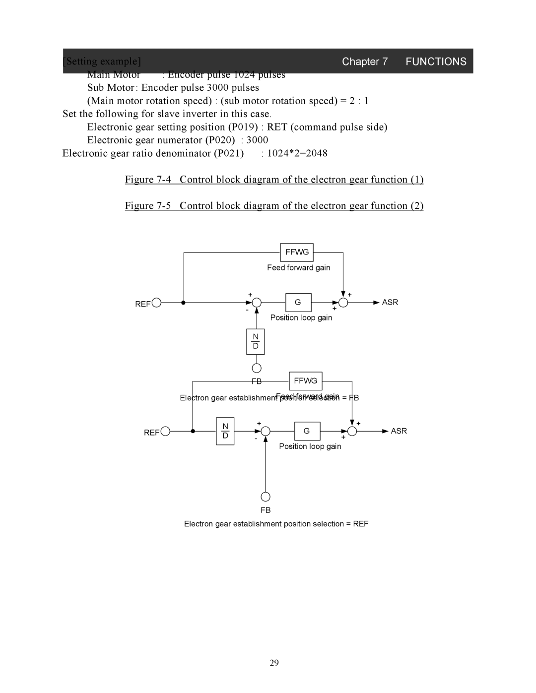
Figure 7-4 Control block diagram of the electron gear function (1)
Figure 7-5 Control block diagram of the electron gear function (2)
REF![]()
FFWG |
|
Feed forward gain |
|
+ | + |
G | ASR |
- | + |
Position loop gain |
|
N |
|
D |
|
|
| FB | FFWG |
| |
|
|
| Feed |
| |
| Electron gear establishment positiforwardn selectiongain = FB |
| |||
| N | + | + |
| |
REF |
| G | ASR | ||
D | - | ||||
| + |
| |||
|
|
| Position loop gain |
| |
FB
Electron gear establishment position selection = REF
29