SECTION 3 – INSTALLATION
NOTE
Be sure that contact tip, liner, and drive rolls are correct for wire size and type. See Section 5 to change parts as needed. See Section 7 for list of other available contact tips.
Review Section
Read entire Section 3 before installing equipment.
1
2
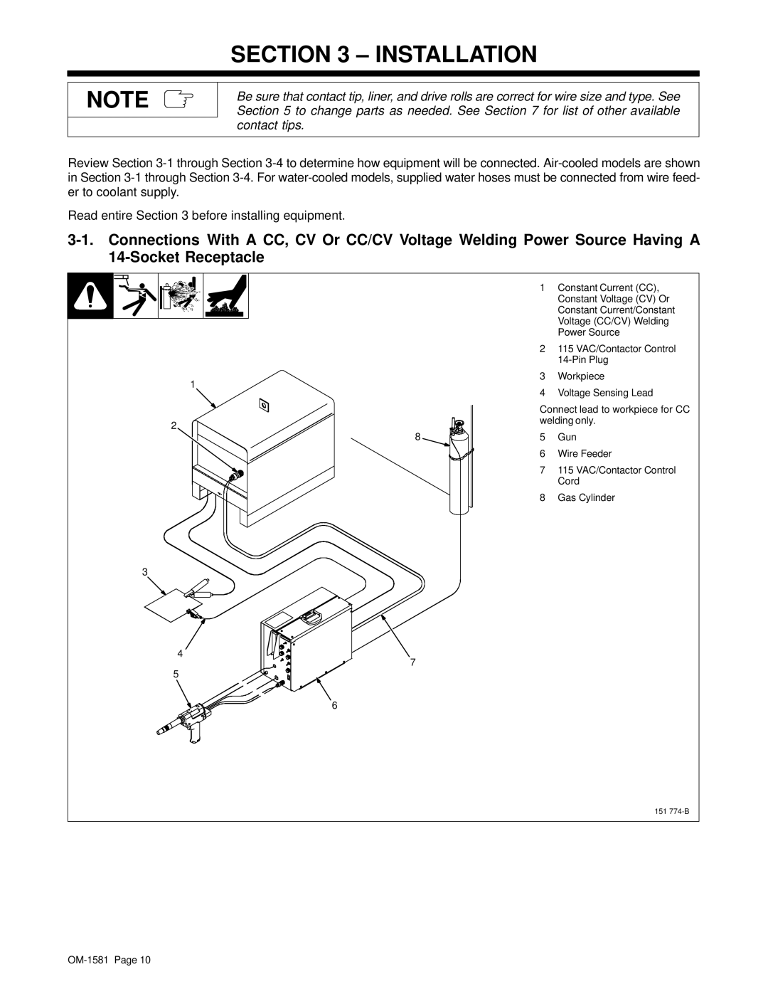
1Constant Current (CC), Constant Voltage (CV) Or Constant Current/Constant Voltage (CC/CV) Welding Power Source
2115 VAC/Contactor Control
3Workpiece
4Voltage Sensing Lead
Connect lead to workpiece for CC welding only.
8 | 5 Gun |
6 Wire Feeder
7115 VAC/Contactor Control Cord
8Gas Cylinder
3
4
7
5
6
151