SECTION 4 – OPERATION
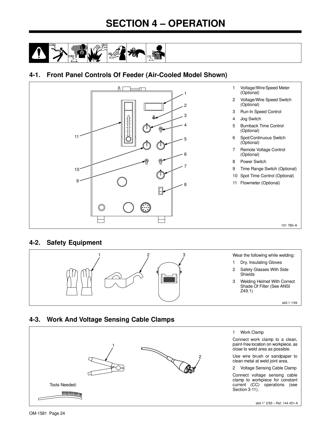
4-1. Front Panel Controls Of Feeder (Air-Cooled Model Shown)
|
| 1 | Voltage/Wire Speed Meter | |
| 1 |
| (Optional) | |
|
| 2 | Voltage/Wire Speed Switch | |
| 2 |
| (Optional) | |
| 3 | 3 | ||
| 4 | Jog Switch | ||
|
| |||
| 4 | 5 | Burnback Time Control | |
|
|
| (Optional) | |
11 | 5 | 6 | Spot/Continuous Switch | |
|
| (Optional) | ||
|
|
| ||
| 6 | 7 | Remote Voltage Control | |
|
| (Optional) | ||
| 7 | 8 | Power Switch | |
10 | 9 | Time Range Switch (Optional) | ||
| ||||
|
| 10 | Spot Time Control (Optional) | |
9 | 8 | 11 | Flowmeter (Optional) | |
| ||||
|
|
|
151
4-2. Safety Equipment
1 | 2 | 3 | Wear the following while welding: |
1 Dry, Insulating Gloves
2 Safety Glasses With Side
Shields
3 Welding Helmet With Correct
Shade Of Filter (See ANSI
Z49.1)
sb3.1 1/94
4-3. Work And Voltage Sensing Cable Clamps
1 Work Clamp
Connect work clamp to a clean,
1paint-free location on workpiece, as close to weld area as possible.
2 | Use wire brush or sandpaper to | ||
| clean metal at weld joint area. | ||
| 2 Voltage Sensing Cable Clamp | ||
| Connect | voltage sensing | cable |
| clamp to workpiece for constant | ||
Tools Needed: | current | (CC) operations | (see |
| Section |
| |
sb4.1* 2/93 – Ref. 144
