Visit our website at
www.HobartWelders.com
| 190 603J |
August 2000
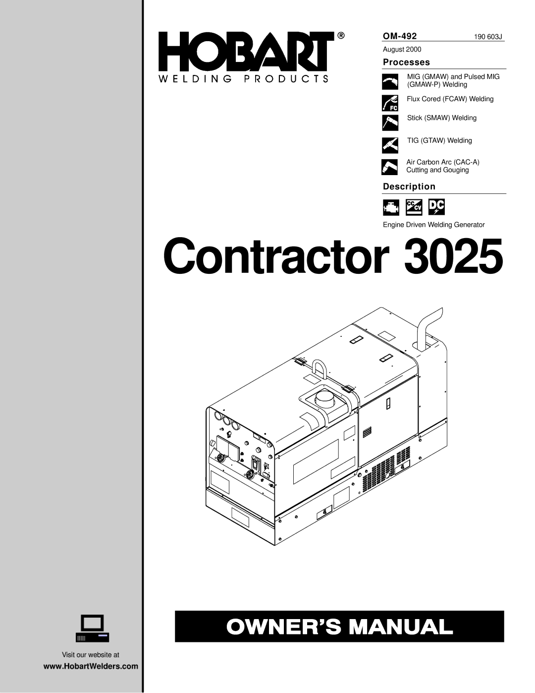
Processes
MIG (GMAW) and Pulsed MIG
Flux Cored (FCAW) Welding
Stick (SMAW) Welding
TIG (GTAW) Welding
Air Carbon Arc
Cutting and Gouging
Description
Engine Driven Welding Generator
Visit our website at
www.HobartWelders.com
| 190 603J |
August 2000
MIG (GMAW) and Pulsed MIG
Flux Cored (FCAW) Welding
Stick (SMAW) Welding
TIG (GTAW) Welding
Air Carbon Arc
Cutting and Gouging
Engine Driven Welding Generator