|
|
|
|
| |
|
|
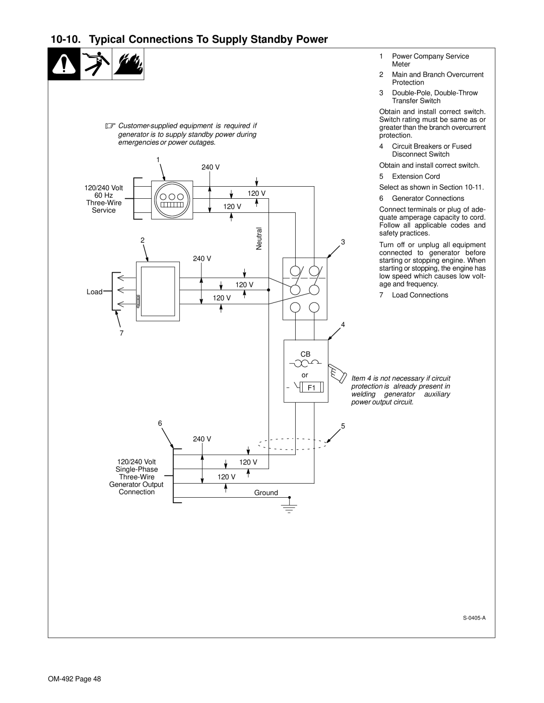
| 1 | Power Company Service | |
|
|
|
| Meter |
|
|
|
| 2 Main and Branch Overcurrent | ||
|
|
|
| Protection | |
|
|
| 3 | ||
|
|
|
| Transfer Switch | |
|
|
| Obtain and install correct switch. | ||
. |
| Switch rating must be same as or | |||
| greater than the branch overcurrent | ||||
generator is to supply standby power during |
| protection. |
| ||
emergencies or power outages. |
| 4 Circuit Breakers or Fused | |||
|
|
| |||
1 |
|
|
| Disconnect Switch | |
240 V |
| Obtain and install correct switch. | |||
|
| ||||
|
|
| 5 | Extension Cord | |
120/240 Volt | 120 V |
| Select as shown in Section | ||
60 Hz |
| 6 | Generator Connections | ||
|
| ||||
120 V |
| Connect terminals or plug of ade- | |||
Service |
| ||||
|
| ||||
|
|
| quate amperage capacity to cord. | ||
| Neutral |
| Follow all | applicable codes and | |
2 |
| safety practices. | |||
|
| ||||
| 3 | Turn off or unplug all equipment | |||
|
|
| |||
| 240 V |
| connected | to generator before | |
|
| starting or stopping engine. When | |||
|
|
| starting or stopping, the engine has | ||
|
|
| low speed which causes low volt- | ||
Load | 120 V |
| age and frequency. | ||
120 V |
| 7 | Load Connections | ||
|
| ||||
|
|
|
|
| |
|
| 4 |
|
|
|
7 |
|
|
|
|
|
| CB |
|
|
|
|
| or | Item 4 is not necessary if circuit | |||
|
| ||||
| F1 | protection is | already present in | ||
|
| welding | generator | auxiliary | |
|
| power output circuit. |
| ||
6 |
| 5 |
|
|
|
|
|
|
|
| |
| 240 V |
|
|
|
|
120/240 Volt | 120 V |
|
|
|
|
|
|
|
|
| |
120 V |
|
|
|
| |
Generator Output |
|
|
|
|
|
Connection | Ground |
|
|
|
|