| 1 |
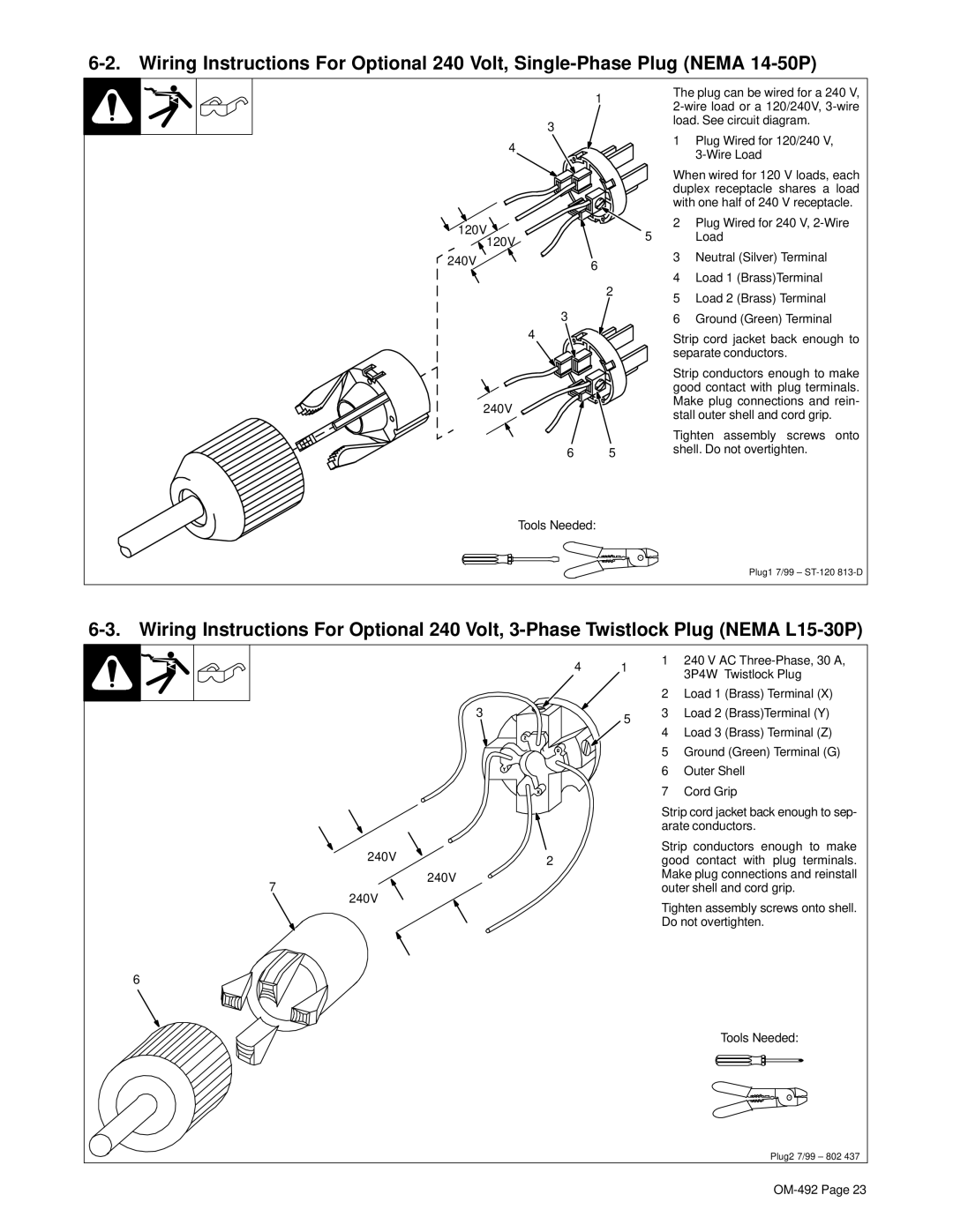
| The plug can be wired for a 240 V, | |
|
| |||
|
|
| ||
3 |
|
| load. See circuit diagram. | |
|
| 1 Plug Wired for 120/240 V, | ||
4 |
|
| ||
|
|
|
| |
|
|
|
| |
|
|
| When wired for 120 V loads, each | |
|
|
| duplex receptacle shares a load | |
|
|
| with one half of 240 V receptacle. | |
120V |
|
| 2 Plug Wired for 240 V, | |
|
| 5 | Load | |
120V |
|
| ||
|
|
|
| |
240V | 6 |
| 3 | Neutral (Silver) Terminal |
|
|
| ||
|
| 4 | Load 1 (Brass)Terminal | |
|
| 2 | ||
|
| 5 Load 2 (Brass) Terminal | ||
|
|
| ||
3 |
|
| 6 | Ground (Green) Terminal |
4 |
|
| Strip cord jacket back enough to | |
|
|
| ||
|
|
| separate conductors. | |
|
|
| Strip conductors enough to make | |
|
|
| good contact with plug terminals. | |
240V |
|
| Make plug connections and rein- | |
|
| stall outer shell and cord grip. | ||
|
|
| ||
|
|
| Tighten assembly screws onto | |
6 |
| 5 | shell. Do not overtighten. | |
|
|
| ||
Tools Needed:
Plug1 7/99 –
4 1
3 | 5 |
|
240V | 2 |
|
240V
7
240V
1240 V AC
2Load 1 (Brass) Terminal (X)
3Load 2 (Brass)Terminal (Y)
4Load 3 (Brass) Terminal (Z)
5Ground (Green) Terminal (G)
6Outer Shell
7Cord Grip
Strip cord jacket back enough to sep- arate conductors.
Strip conductors enough to make good contact with plug terminals. Make plug connections and reinstall outer shell and cord grip.
Tighten assembly screws onto shell. Do not overtighten.
6
Tools Needed:
Plug2 7/99 – 802 437