7-9. Voltmeter/Ammeter Help Displays
VA
1
![]() HE.L
HE.L
| V |
| A |
2 | HE.L |
| |
|
| ||
|
|
|
|
| V |
| A |
3
![]() HE.L
HE.L
| V |
| A |
4 |
|
|
|
HE.L |
| ||
|
| ||
|
|
|
|
| V |
| A |
5
![]() HE.L
HE.L
VA
6
![]() HE.L
HE.L
| V |
| A |
7 | HE.L |
| |
|
| ||
|
|
|
|
| V |
| A |
8
![]() HE.L
HE.L
| V |
| A |
9 |
|
|
|
HE.L |
| ||
|
| ||
|
|
|
|
| V |
| A |
10
 HE.L
HE.L P–9
802
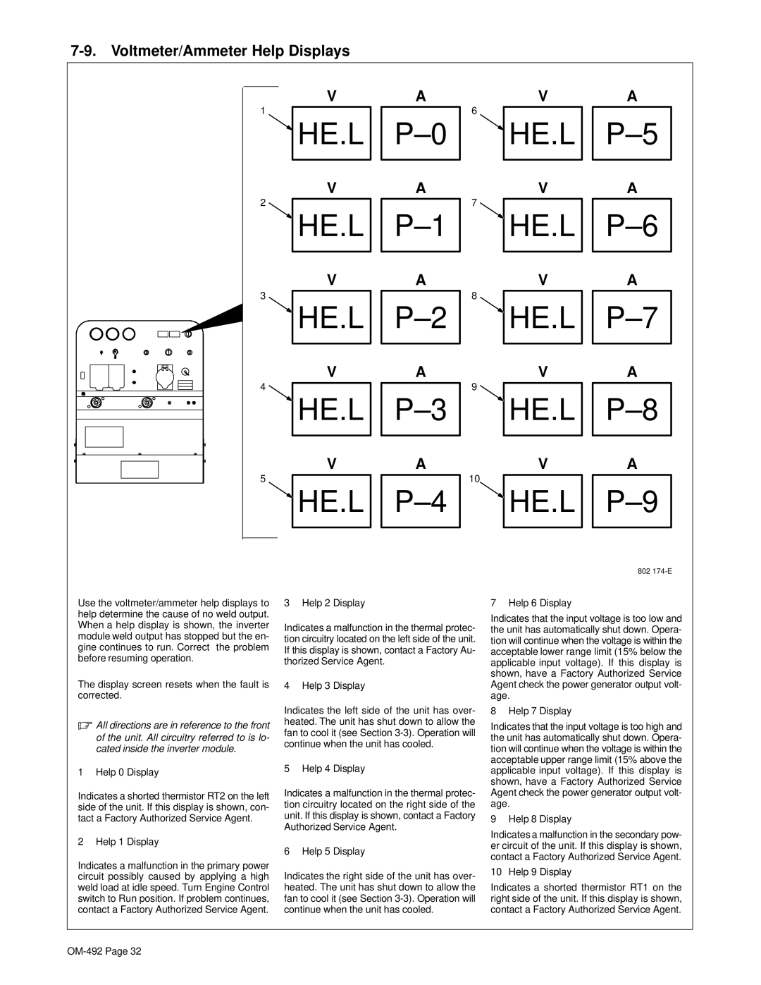
Use the voltmeter/ammeter help displays to help determine the cause of no weld output. When a help display is shown, the inverter module weld output has stopped but the en- gine continues to run. Correct the problem before resuming operation.
The display screen resets when the fault is corrected.
.All directions are in reference to the front of the unit. All circuitry referred to is lo- cated inside the inverter module.
1 Help 0 Display
Indicates a shorted thermistor RT2 on the left side of the unit. If this display is shown, con- tact a Factory Authorized Service Agent.
2 Help 1 Display
Indicates a malfunction in the primary power circuit possibly caused by applying a high weld load at idle speed. Turn Engine Control switch to Run position. If problem continues, contact a Factory Authorized Service Agent.
3 Help 2 Display
Indicates a malfunction in the thermal protec- tion circuitry located on the left side of the unit. If this display is shown, contact a Factory Au- thorized Service Agent.
4 Help 3 Display
Indicates the left side of the unit has over- heated. The unit has shut down to allow the fan to cool it (see Section
5 Help 4 Display
Indicates a malfunction in the thermal protec- tion circuitry located on the right side of the unit. If this display is shown, contact a Factory Authorized Service Agent.
6 Help 5 Display
Indicates the right side of the unit has over- heated. The unit has shut down to allow the fan to cool it (see Section
7 Help 6 Display
Indicates that the input voltage is too low and the unit has automatically shut down. Opera- tion will continue when the voltage is within the acceptable lower range limit (15% below the applicable input voltage). If this display is shown, have a Factory Authorized Service Agent check the power generator output volt- age.
8 Help 7 Display
Indicates that the input voltage is too high and the unit has automatically shut down. Opera- tion will continue when the voltage is within the acceptable upper range limit (15% above the applicable input voltage). If this display is shown, have a Factory Authorized Service Agent check the power generator output volt- age.
9 Help 8 Display
Indicates a malfunction in the secondary pow- er circuit of the unit. If this display is shown, contact a Factory Authorized Service Agent.
10 Help 9 Display
Indicates a shorted thermistor RT1 on the right side of the unit. If this display is shown, contact a Factory Authorized Service Agent.