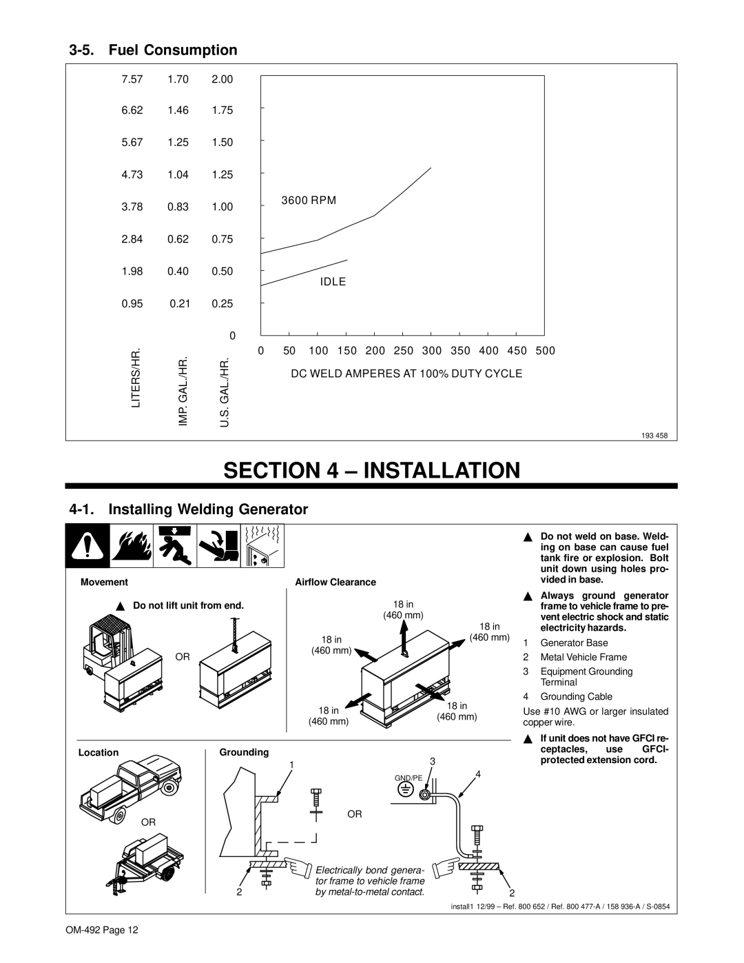
3-5. Fuel Consumption
7.57 1.70 2.00
6.62 1.46 1.75
5.67 1.25 1.50
4.73 1.04 1.25
3.78 0.83 1.00
2.84 0.62 0.75
3600 RPM
1.98 | 0.40 | 0.50 |
0.95 | 0.21 | 0.25 |
|
| 0 |
LITERS/HR. | IMP. GAL./HR. | U.S. GAL./HR. |
IDLE
050 100 150 200 250 300 350 400 450 500 DC WELD AMPERES AT 100% DUTY CYCLE
193 458
SECTION 4 – INSTALLATION
4-1. Installing Welding Generator
Movement |
| Airflow Clearance |
|
Y Do not lift unit from end. | 18 in |
| |
|
| (460 mm) |
|
|
|
| 18 in |
|
| 18 in | (460 mm) |
| OR | (460 mm) |
|
|
|
| |
|
| 18 in | 18 in |
|
| (460 mm) | |
|
| (460 mm) | |
|
|
| |
Location | Grounding |
| 3 |
|
| 1 | |
|
| 4 | |
|
| GND/PE | |
|
|
| |
| OR | OR |
|
|
|
| |
|
| Electrically bond genera- |
|
|
| tor frame to vehicle frame |
|
| 2 | by | 2 |
YDo not weld on base. Weld- ing on base can cause fuel tank fire or explosion. Bolt unit down using holes pro- vided in base.
YAlways ground generator frame to vehicle frame to pre- vent electric shock and static electricity hazards.
1Generator Base
2Metal Vehicle Frame
3Equipment Grounding Terminal
4Grounding Cable
Use #10 AWG or larger insulated copper wire.
YIf unit does not have GFCI re-
ceptacles, use GFCI- protected extension cord.
install1 12/99 – Ref. 800 652 / Ref. 800