SYSTEM OVERVIEW
About the Display and Indicators
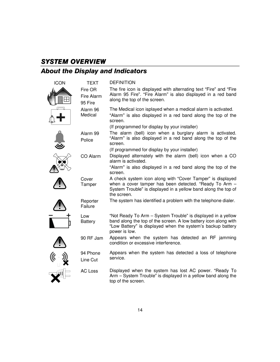
ICONTEXT
Fire OR
Fire Alarm
95 Fire
Alarm 96
Medical
Alarm 99
Police
CO Alarm
Cover
Tamper
Reporter
Failure
Low
Battery
90 RF Jam
94 Phone
Line Cut
AC Loss
DEFINITION
The fire icon is displayed with alternating text “Fire” and “Fire Alarm 95 Fire”. “Fire Alarm” is also displayed in a red band along the top of the screen.
The Medical icon isplayed when a medical alarm is activated. “Alarm” is also displayed in a red band along the top of the screen.
(If programmed for display by your installer)
The alarm (bell) icon when a burglary alarm is activated. “Alarm” is also displayed in a red band along the top of the screen.
(If programmed for display by your installer)
Displayed alternately with the alarm (bell) icon when a CO alarm is activated.
“Alarm” is also displayed in a red band along the top of the screen.
A check system icon along with “Cover Tamper” is displayed when a cover tamper has been detected. “Ready To Arm – System Trouble” is displayed in a yellow band along the top of the screen.
The system has identified a problem with the telephone dialer.
“Not Ready To Arm – System Trouble” is displayed in a yellow band along the top of the screen. A low battery icon along with “Low Battery” is displayed when the system’s backup battery power is low.
Appears when the system has detected an RF jamming condition or excessive interference.
Appears when the system has detected a loss of telephone service.
Displayed when the system has lost AC power. “Ready To Arm – System Trouble” is displayed in a yellow band along the top of the screen.
– 14 –