Manuals
/
Hoshizaki
/
Kitchen Appliance
/
Ice Maker
Hoshizaki
FS-1022MLH-C
service manual
Wiring Diagrams
Models:
FS-1022MLH-C
1
23
57
57
Download
57 pages
3.7 Kb
20
21
22
23
24
25
26
27
Specifications
Sequence Flow Chart
Shutdown Delay
Maintenance
Diagnostic Procedure
Evaporator Assembly
Sanitizing Procedure Initial
Controls and Adjustments
Float Switch Cleaning
Refrigerant Recovery
Page 23
Image 23
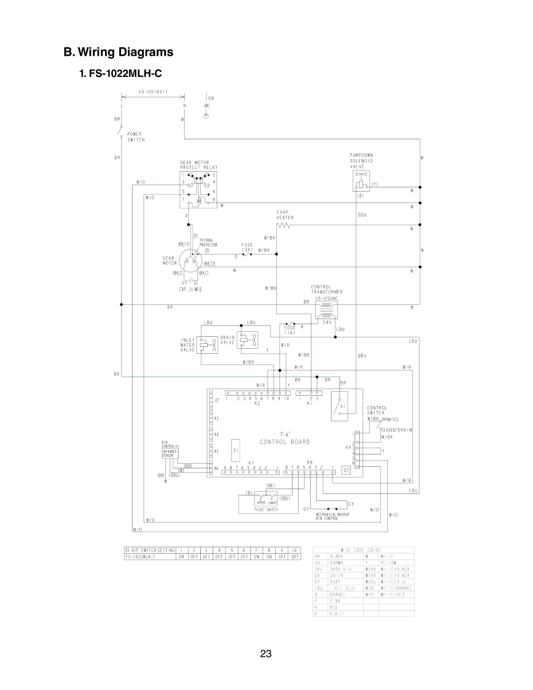
B. Wiring Diagrams
1.
FS-1022MLH-C
23
Page 22
Page 24
Page 23
Image 23
Page 22
Page 24
Contents
SRC-10H
Hoshizaki AMERICA, INC
Contents
Page
Unit
Important Safety Information
Serious injury
Indicates important information about the use and care
For SRC
FS-1022MLH-C
Specifications Icemaker
SRC-10H
Condensing Unit
Icemaker FS-1022MLH-C
II. General Information Construction
Condensing Unit a SRC-10H
Icemaking Unit
Sequence Cycles and Shutdown
Sequence of Operation
Drain Cycle
Shutdown Cycle
Sequence Flow Chart
Control Board Sequence Flow Chart FS-1022MLH-C/SRC-10H
Control Board
Control Board
Control Board Layout
Energized Components Min Max
LED Lights and Audible Alarm Safeties
No. of Beeps Type of Alarm Reset Options Every 5 sec
Sequence Step
Seconds 1.6 minutes Factory Default
Controls and Adjustments
S1 Dip Switch Setting Infrared Sensor Shutdown Delay
S1 Dip Switch Setting Dispense Time
S1 Dip Switch Setting Drain Timer Interval
Bin Control
S1 Dip Switch Mechanical
Backup
Shutdown Delay
III
Wiring Diagrams
High-Pressure Switch
Control Low-Pressure Switch
Safety Low-Pressure Switch Manual Reset
FS-1022MLH-C with SRC-10H
Performance Data
Ice Production Check
IV. Service Diagnosis
Diagnostic Procedure
Page
Page
Page
Control Board Check
5VDC
Page
Infrared Sensor Check
Bin Control Check
Mechanical Backup Bin Control Check
Page
Float Switch Cleaning
Float Switch Check and Cleaning
Float Switch Check
Page
No Ice Production Possible Cause Startup
Diagnostic Charts
No Ice Production
No Ice Production Possible Cause
Shutdown
Service for Refrigerant Lines
Removal and Replacement of Components
Evacuation and Recharge R-404A
Refrigerant Recovery
Brazing
Component
Important Notes for Component Replacement
Evaporator Assembly Components. See Fig
Evaporator Assembly
Upper Bearing Wear Check
Removal and Replacement of Cutter
Removal and Replacement of Auger
Removal and Replacement of Extruding Head
Removal and Replacement of Evaporator
Page
Removal and Replacement of Gear Motor
6b. Lower Housing
Page
Cleaning Procedure
VI. Cleaning and Maintenance
Cleaning and Sanitizing Instructions
Cleaning Solution
Float Switch Assembly Reservoir Cover
Sanitizing Procedure Initial
Sanitizing Solution
Sanitizing Procedure Final
Maintenance
Frequency Area Task
Maintenance Schedule
Drain the evaporator
Preparing the Icemaker for Long Storage
Remove the water from the icemaker water supply line
Top
Page
Image
Contents