B. Important Notes for Component Replacement
CAUTION
When replacing a component listed below, see the notes to help ensure proper operation.
Component |
| Notes |
|
| |
Compressor | Install a new start capacitor, run capacitor, and start relay. | |
|
| |
Expansion Valve | • Attach the expansion valve bulb to the suction line in the same location as the previous | |
| bulb. |
|
| • The bulb should be between the 10 and 2 o'clock position on the tube. | |
| • Secure the bulb with the clamp and holder, then insulate it. | |
|
| |
Hot Gas Valve | • Replace the strainer when replacing the hot gas valve. | |
Liquid Line Valve | • Use copper tube of the same diameter and length when replacing valve lines. | |
Fan Motor | Install a new capacitor. |
|
|
|
|
Pump Motor | Install a new capacitor. |
|
|
| |
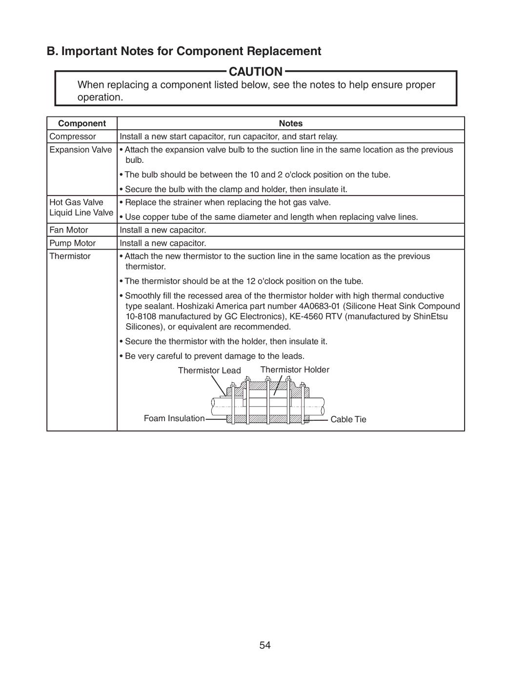
Thermistor | • Attach the new thermistor to the suction line in the same location as the previous | |
| thermistor. |
|
| • The thermistor should be at the 12 o'clock position on the tube. | |
| • Smoothly fill the recessed area of the thermistor holder with high thermal conductive | |
| type sealant. Hoshizaki America part number | |
| ||
| Silicones), or equivalent are recommended. | |
| • Secure the thermistor with the holder, then insulate it. | |
| • Be very careful to prevent damage to the leads. | |
| Thermistor Lead | Thermistor Holder |
Foam Insulation |
| Cable Tie |
|
54