KM-630MRF, KM-630MWF, KM-630MAF specifications
The Hoshizaki KM-630MWF, KM-630MAF, and KM-630MRF are advanced commercial ice machines designed to meet the needs of various businesses, including restaurants, bars, and cafes. Renowned for their efficiency, durability, and performance, these models showcase Hoshizaki's dedication to innovation in the foodservice industry.One of the primary features of the Hoshizaki KM-630 series is the production of crescent-shaped ice. This type of ice is not only aesthetically pleasing but also known for its slow melting properties, making it ideal for keeping beverages cold without diluting them quickly. With a production capacity of up to 617 pounds of ice per day, these machines are built to handle high-demand scenarios efficiently.
The KM-630MWF model is equipped with a water-cooled condenser, making it suitable for environments where air-cooled units might face challenges due to high ambient temperatures. In contrast, the KM-630MAF features an air-cooled condenser which is advantageous for businesses looking to reduce water usage. The KM-630MRF variant utilizes a remote-cooled option, offering flexibility in installation and reducing heat and noise in the kitchen areas.
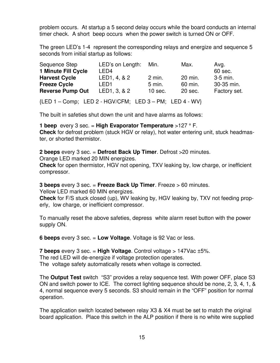
All three models are built with superior quality stainless steel, ensuring durability and resistance to rust and corrosion. They are designed to be easy to clean, featuring a smooth surface that minimizes dirt and bacteria buildup. Furthermore, Hoshizaki incorporates their advanced EverCheck alert system, providing operators with real-time performance notifications and ensuring reliable operation.
Energy efficiency is a crucial characteristic of the KM-630 series. These machines are designed to comply with industry standards, significantly reducing energy consumption and operating costs. Their highly efficient refrigeration system not only enhances ice production but also extends the lifespan of the machine.
In terms of ease of use, Hoshizaki has designed the KM-630 series to feature a user-friendly control panel. This panel allows for straightforward monitoring and modification of operations, ensuring operators can manage the machine effectively.
Overall, the Hoshizaki KM-630MWF, KM-630MAF, and KM-630MRF ice machines represent a blend of advanced technology, energy efficiency, and robust construction, making them an ideal choice for businesses that demand high-quality ice production. With their innovative features, these machines are poised to elevate the service capabilities of any establishment.
