5.Remove the rear cover (see Rear cover on page 26).
6.Disconnect the battery cable (see Hard drive on page 27). Remove the
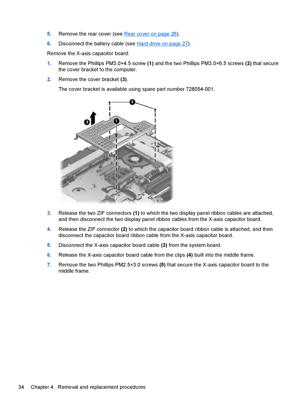
1.Remove the Phillips PM3.0×4.5 screw (1) and the two Phillips PM3.0×6.5 screws (2) that secure the cover bracket to the computer.
2.Remove the cover bracket (3).
The cover bracket is available using spare part number
3.Release the two ZIF connectors (1) to which the two display panel ribbon cables are attached, and then disconnect the two display panel ribbon cables from the
4.Release the ZIF connector (2) to which the capacitor board ribbon cable is attached, and then disconnect the capacitor board ribbon cable from the
5.Disconnect the
6.Release the
7.Remove the two Phillips PM2.5×3.0 screws (5) that secure the
34 Chapter 4 Removal and replacement procedures
