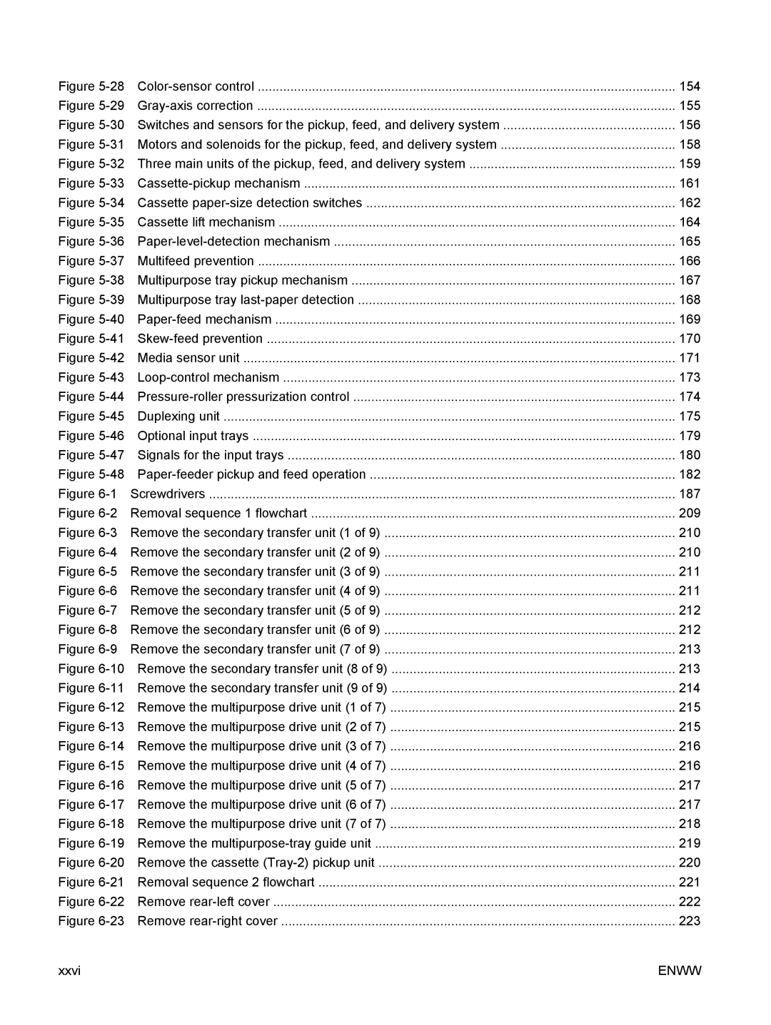
Figure 5-28 | Color-sensor control | 154 |
Figure 5-29 | Gray-axis correction | 155 |
Figure 5-30 Switches and sensors for the pickup, feed, and delivery system | 156 |
Figure 5-31 Motors and solenoids for the pickup, feed, and delivery system | 158 |
Figure 5-32 Three main units of the pickup, feed, and delivery system | 159 |
Figure 5-33 | Cassette-pickup mechanism | 161 |
Figure 5-34 Cassette paper-size detection switches | 162 |
Figure 5-35 Cassette lift mechanism | 164 |
Figure 5-36 | Paper-level-detection mechanism | 165 |
Figure 5-37 | Multifeed prevention | 166 |
Figure 5-38 Multipurpose tray pickup mechanism | 167 |
Figure 5-39 Multipurpose tray last-paper detection | 168 |
Figure 5-40 | Paper-feed mechanism | 169 |
Figure 5-41 | Skew-feed prevention | 170 |
Figure 5-42 Media sensor unit | 171 |
Figure 5-43 | Loop-control mechanism | 173 |
Figure 5-44 Pressure-roller pressurization control | 174 |
Figure 5-45 | Duplexing unit | 175 |
Figure 5-46 Optional input trays | 179 |
Figure 5-47 Signals for the input trays | 180 |
Figure 5-48 Paper-feeder pickup and feed operation | 182 |
Figure 6-1 | Screwdrivers | 187 |
Figure 6-2 Removal sequence 1 flowchart | 209 |
Figure 6-3 Remove the secondary transfer unit (1 of 9) | 210 |
Figure 6-4 Remove the secondary transfer unit (2 of 9) | 210 |
Figure 6-5 Remove the secondary transfer unit (3 of 9) | 211 |
Figure 6-6 Remove the secondary transfer unit (4 of 9) | 211 |
Figure 6-7 Remove the secondary transfer unit (5 of 9) | 212 |
Figure 6-8 Remove the secondary transfer unit (6 of 9) | 212 |
Figure 6-9 Remove the secondary transfer unit (7 of 9) | 213 |
Figure 6-10 Remove the secondary transfer unit (8 of 9) | 213 |
Figure 6-11 Remove the secondary transfer unit (9 of 9) | 214 |
Figure 6-12 Remove the multipurpose drive unit (1 of 7) | 215 |
Figure 6-13 Remove the multipurpose drive unit (2 of 7) | 215 |
Figure 6-14 Remove the multipurpose drive unit (3 of 7) | 216 |
Figure 6-15 Remove the multipurpose drive unit (4 of 7) | 216 |
Figure 6-16 Remove the multipurpose drive unit (5 of 7) | 217 |
Figure 6-17 Remove the multipurpose drive unit (6 of 7) | 217 |
Figure 6-18 Remove the multipurpose drive unit (7 of 7) | 218 |
Figure 6-19 Remove the multipurpose-tray guide unit | 219 |
Figure 6-20 Remove the cassette (Tray-2) pickup unit | 220 |
Figure 6-21 Removal sequence 2 flowchart | 221 |
Figure 6-22 Remove rear-left cover | 222 |
Figure 6-23 Remove rear-right cover | 223 |
